Gate valve

A gate valve and valve sleeve technology, applied in the direction of sliding valve, valve detail, valve device, etc., can solve the problem of not being able to close completely.

Inactive Publication Date: 2006-08-30
INTERFORGE KLEE
View PDF0 Cites 1 Cited by
  • Summary
  • Abstract
  • Description
  • Claims
  • Application Information

AI Technical Summary

Problems solved by technology

The result is: the valve must first be closed with a greater co

Method used


Image

  • Gate valve
  • Gate valve
  • Gate valve

Examples


Embodiment Construction

[0025] In the following description of embodiments by way of example, terms such as "left", "right", "top", "bottom", "inner", "outer", "vertical" or "horizontal" Corresponds to the description of the valve in the accompanying drawings. These terms have been chosen only to facilitate the existing description and in no way be considered as limiting the scope of protection of the described valve, which can be installed in any spatial position.

[0026] The components of the valve are first described with reference to an exemplary embodiment. Components having the same function are numbered in the same way in the figures.

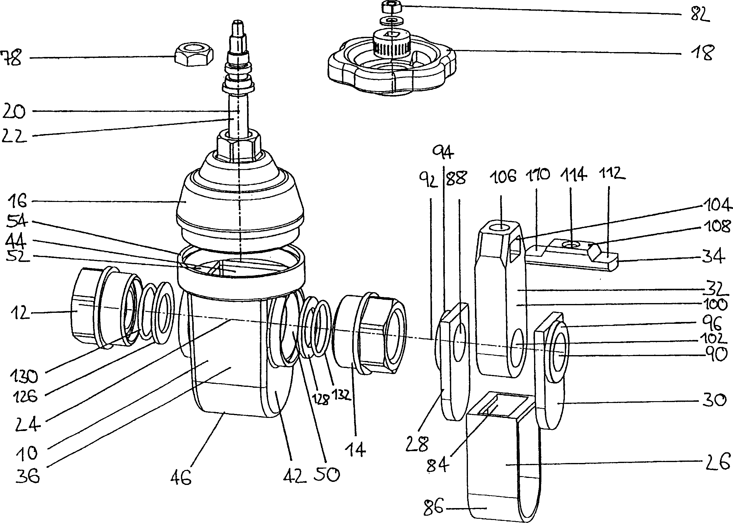
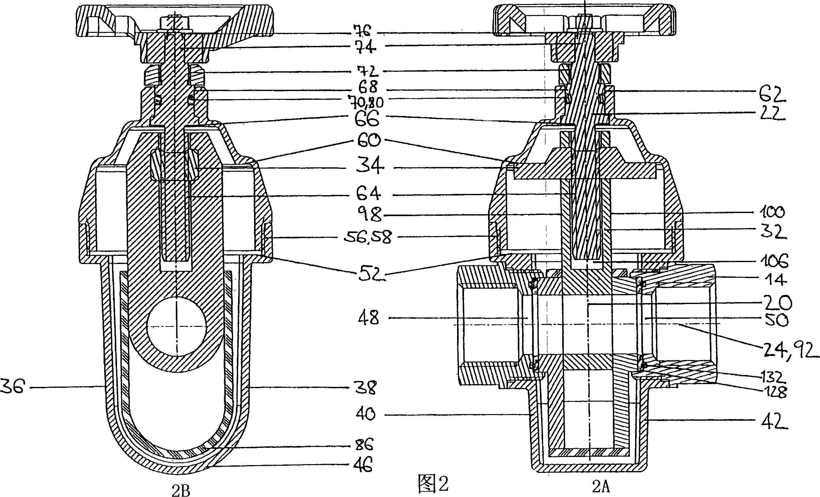
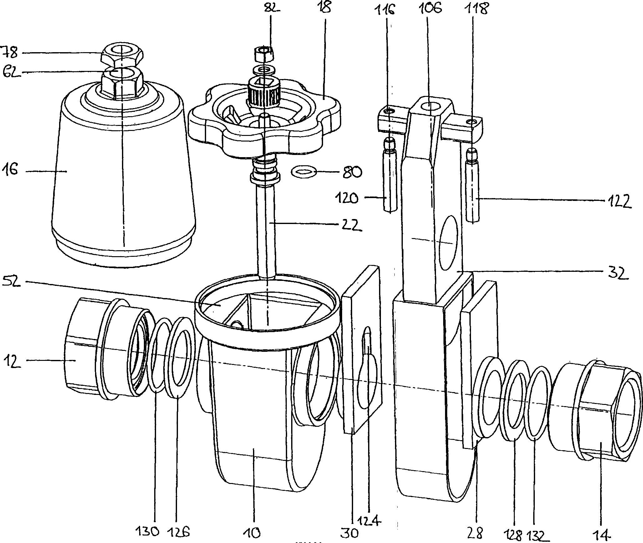
[0027] The valve, especially for liquids, has a valve housing 10, connecting members 12 and 14 for input and output, a cover 16 on the valve housing 10, and a valve shaft 22 which can pass through an actuating member— For example a hand wheel 18 - which rotates about a vertical axis 20 . In the illustrated embodiment, the connecting members 12 , 14 are arra...


PUM


Abstract

A gate valve comprising a valve housing with connection openings disposed in mutually opposite relationship on a first common axis, and also connection elements for the inlet and outlet of a fluid, a cap on the valve housing and a valve actuation means coupled to a sliding gate. It is provided therein that arranged in the valve housing are: a hollow cage having a first and a second end face of which the first end face has an insertion opening, further with two mutually oppositely disposed fixed side walls and two parallel mutually oppositely disposed free side walls which are formed by two separate side plates with through bores which in the installed condition are on a second common axis, the sliding gate which has a through-flow opening is introduced through the insertion opening of the cage and is guided sealingly in the cage and between the side plates and the side plates bear with their respective inward side in surface contact against the sliding gate, the sliding gate has two end positions so that in a first opened end position the through-flow opening of the sliding gate coincides completely with the diameter of the through bores of the side plates in the installed condition and in a second closed end position the through-flow opening of the sliding gate is completely outside the diameter of the through bores of the side plates.

Description

technical field [0001] The present invention relates to a gate valve comprising a valve sleeve having connecting ports opposite to each other arranged on a first common axis; and connecting members for inflow and outflow of fluid; a The upper cover and a valve actuator combined to a sliding door. Background technique [0002] Gate valves of different constructions are known. Conventional shallow wedge sliding doors have a wedge-shaped closing member that is forced into a wedge-shaped receiver when the valve is closed. In this case, the integrity of the seal depends on the contact pressure. When the valve is open, deposits, so-called fouling, are formed which build up when the wedge member is closed and are forced into the wedge holder. The result is that first the valve must be closed with a greater contact pressure, and the valve can no longer be closed completely. Contents of the invention [0003] It is an object of the present invention to provide a gate valve in w...

Claims


Application Information

Patent Timeline
IPC IPC(8): F16K3/02
CPCF16K3/02F16K31/508
Inventor 克劳斯·克莱
Owner INTERFORGE KLEE
Why Eureka
Try Eureka