Rotating table device of machine tool

A technology of rotary table and machine tool, used in manufacturing tools, metal processing equipment, metal processing machine parts, etc., can solve the problems of low work efficiency, decreased rigidity of rotary table, unusable clamping mechanism, etc.

Inactive Publication Date: 2010-07-21
WUHU HENGSHENG HEAVY MACHINE TOOL
View PDF3 Cites 9 Cited by
  • Summary
  • Abstract
  • Description
  • Claims
  • Application Information

AI Technical Summary

Problems solved by technology

[0002] At present, the rotary indexing movement of the worktable of the rotary table device of the machine tool is generally driven by the inner ring gear. The clamping mechanism of the rotary table is generally provided with four clamping points on the four corners of the slide seat. The external design of the ring is used for clamping; when the rotary table is rotated by the external ring gear, it is restricted by other factors such as structure and space, and the clamping mechanism of the external clamping method cannot be used, and the rotary work The clamping mechanism is arranged inside the table. The existing internal clamping method of the rotary table is to open holes on the rotary table and install the clamping mechanisms one by one, which not only destroys the integrity of the rotary table, but also leads to the failure of the rotary table. Decreased rigidity, inconvenient installation, more difficult maintenance, and lower work efficiency

Method used


Image

  • Rotating table device of machine tool
  • Rotating table device of machine tool
  • Rotating table device of machine tool

Examples


Embodiment Construction

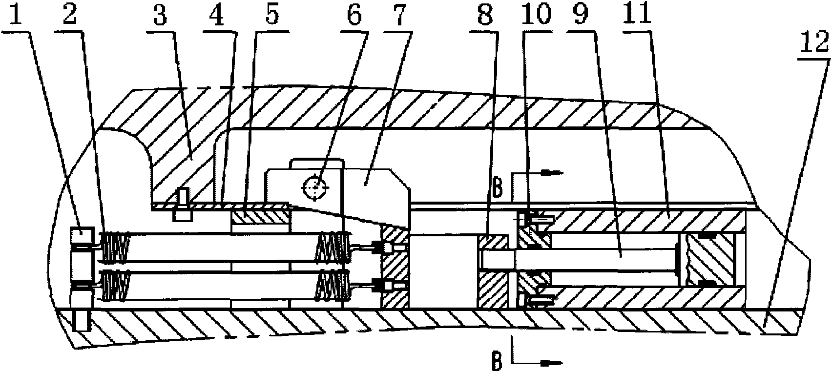
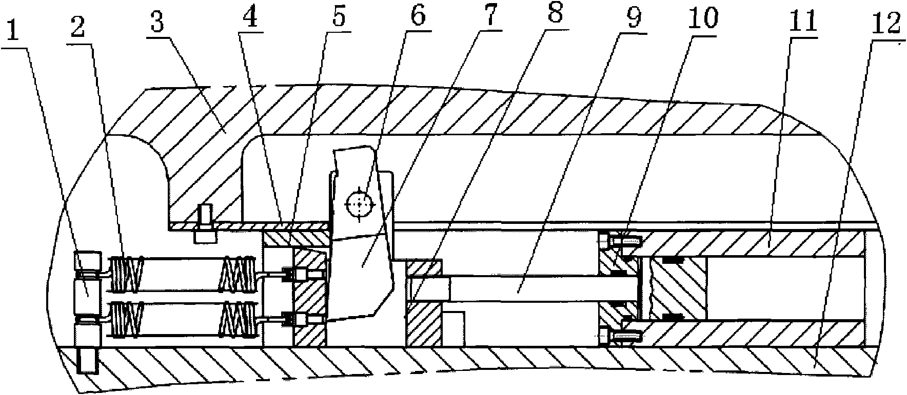
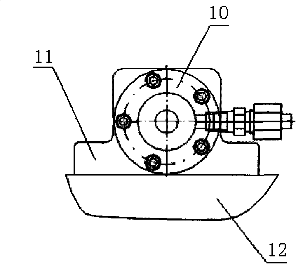
[0013] Such as figure 1 , figure 2 , image 3 As shown, a machine tool rotary table device includes a rotary table 3, a sliding seat 12 and a plurality of hydraulic clamping parts of the same structure evenly distributed around the rotary table 3, each hydraulic clamping part includes a rotary table 3 and the oil cylinder 11 between the sliding seat 12, the pin shaft 6 fixed on the side of the rotary table 3, the pin 1 fixed on the sliding seat 12, the annular pressing piece 4 fixed on the lower part of the rotary table 3, and the The fixed support 5 below the compression piece 4, the pressure plate 7 rotating around the pin shaft 6, the tension spring 2 and the wedge 8, one end of the tension spring 2 is connected to the pin 1, and the other end of the tension spring 2 is connected to the wedge 8 Connection, the wedge 8 is affixed to the end of the piston rod 9 of the oil cylinder, and the center of gravity of the pressure plate 7 is located on the side of the center line ...


PUM


Abstract

The invention discloses a rotating table device of a machine tool. The rotating table device comprises a rotating table, a sliding seat and a plurality of hydraulic-clamping parts with the same structure, wherein the hydraulic-clamping parts are evenly distributed at the periphery of the rotating table; each hydraulic-clamping part comprises a cylinder arranged between the rotating table and the sliding seat, a hinge pin fixed at the side face of the rotating table, a pin column fixed at the sliding seat, an annular compaction piece arranged at the lower part of the rotating table, a fixed bearing below the annular compaction piece, a pressure pad capable of rotating around the hinge pin, a tension spring and a wedge block; one end of the tension spring is connected with the pin column, and the other end of the tension spring is connected with the wedge block; the wedge block is fixedly connected to the end part of a piston rod of the cylinder; and when the pressure pad is at a compaction position, one end of the pressure pad is laminated with the annular compaction piece, and the lower surface of the other end of the pressure pad is abutted with the inclined plane of the wedge block. By adopting the structure, the rotating table device of the machine tool of the invention facilitates the operation of workers, can ensure the working reliability, can reduce the work load of installation and maintenance, and improves the working efficiency.

Description

technical field [0001] The invention relates to machine tools, in particular to a machine tool rotary table device. Background technique [0002] At present, the rotary indexing movement of the worktable of the rotary table device of the machine tool is generally driven by the inner ring gear. The clamping mechanism of the rotary table is generally provided with four clamping points on the four corners of the slide seat. The external design of the ring is used for clamping; when the rotary table is rotated by the external ring gear, it is restricted by other factors such as structure and space, and the clamping mechanism of the external clamping method cannot be used, and the rotary work The clamping mechanism is arranged inside the table. The existing internal clamping method of the rotary table is to open holes on the rotary table and install the clamping mechanisms one by one, which not only destroys the integrity of the rotary table, but also leads to the failure of the ...

Claims


Application Information

Patent Timeline
IPC IPC(8): B23Q1/25
Inventor 胡子俊丰云杨荷妹施跃敏
Owner WUHU HENGSHENG HEAVY MACHINE TOOL
Why Eureka
Try Eureka