
Structure of water jet blade

A technology of cutter heads and water jets, applied in the direction of explosion generating devices, abrasives, metal processing equipment, etc., can solve problems such as multi-processing waste, complexity of secondary processing procedures, uneven water pressure in water outlet holes, etc.

Inactive Publication Date: 2010-07-21
厦门喜儿工贸有限公司
View PDF0 Cites 2 Cited by
  • Summary
  • Abstract
  • Description
  • Claims
  • Application Information

AI Technical Summary

Problems solved by technology

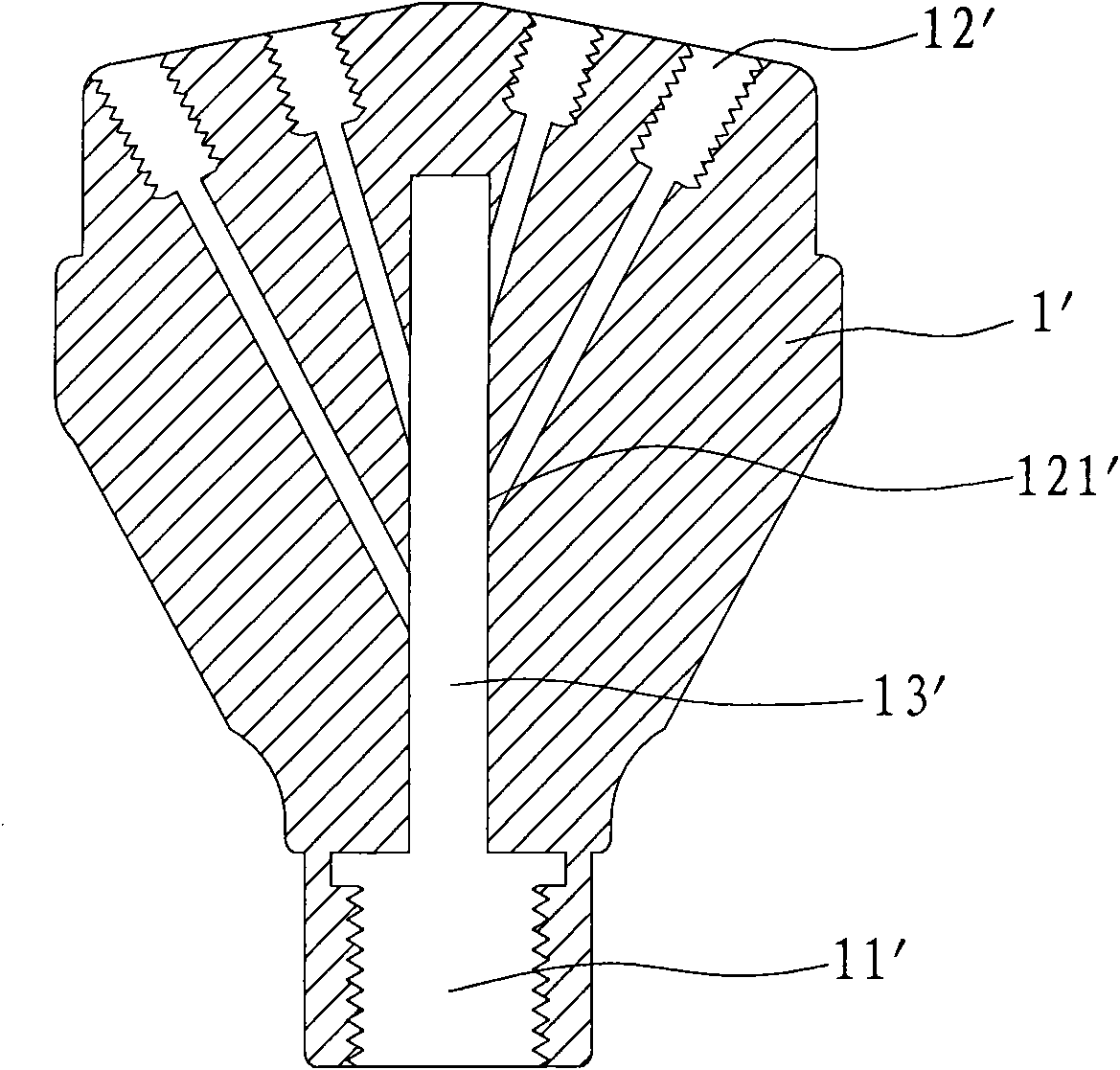
[0003] Cooperate figure 1 As shown in the schematic diagram of the structure, the traditional cutter head is an integral cutter head 1' processed from an integral stainless steel block, and then the secondary machining of the water outlet hole 12' and the water inlet hole 11' is performed on the cutter head 1', and the The water hole 11' extends from the rear of the cutter head to the inside of the cutter head to form a column cavity, and each water outlet hole 12' communicates with the column cavity 13' respectively. It can be seen that the water inlet 121' of each water outlet hole 12' is distributed. On the column cavity 13', the lengths of the water outlets are different. The water pressure at the front of the column cavity 13' must be greater than the water pressure at the side, which will inevitably lead to uneven water pressure at each water outlet. This is One of the defects of poor performance of the current cutter head; in addition, the distribution structure of the water outlet holes 12' also determines that the overall cutter head 1' requires more materials, and the second processing method of each water outlet hole 12'column cavity 13' , will also produce more processing waste, so the material cost is high, and the complexity of the secondary processing process is also the reason why the current price of the cutter head remains high

Method used


Image

  • Structure of water jet blade
  • Structure of water jet blade
  • Structure of water jet blade

Examples


Embodiment Construction

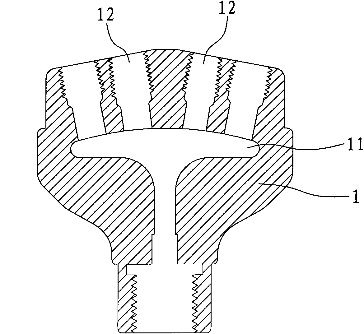
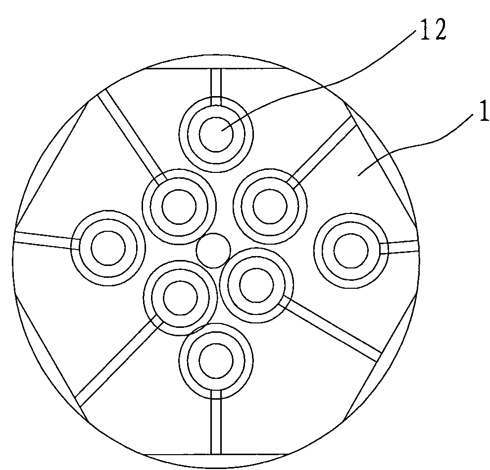
[0012] Such as figure 2 , 3 As shown, the present invention discloses a waterjet cutter head structure, the cutter head gradually expands from the rear to the front to form a tapered body 1, and at the same time, a tapered chamber 11 that gradually expands from the rear to the front is formed in the body 1 , the conical chamber 11 is formed in response to the shape of the conical body 1 to ensure uniform wall thickness between the body 1 and the chamber 11; a plurality of water outlet holes 12 communicating with the front end of the body 1 are formed at the bottom of the chamber 11 , The front end of each water outlet hole 12 is formed with a vertical guide portion to ensure that the water flow is sprayed downward.

[0013] The formation of the chamber 11 here is to ensure that the lengths of the water channels of the water outlet holes 12 are similar, and the pressure of the water flow ejected from the water outlet holes 12 is also similar, so that the water outlet pressure...


PUM


Abstract

The invention discloses a structure of a water jet blade. The blade expands from a back part toward a front part to form a conical body; a conical cavity gradually expanding from the back to the front is formed in the body; and a plurality of water outlets communicated with the front end of the body are formed on the bottom part of the cavity. The formation of the conical cavity in the body of the blade ensures that both the lengths of the water channels of the water outlets and the pressures of he water flows sprayed out from the water outlets are similar and that the effluent pressure of the water jet blade is uniform; the formation of the cavity promotes the formation of a reservoir in the blade, water enters the reservoir under the action of the pressure applied on a water source is buffered in the reservoir and the pressures provided by the reservoir for the water outlet are uniform, so the working performance of the blade is improved effectively; the reservoir has a bigger volume than the cylindrical cavity in the traditional blade, so the bland is casted with less material; and thus, the material cost of the use of the blade is reduced effectively and the water jet blade is more competitive in the market.

Description

technical field [0001] The invention relates to a water jet facility for grinding and processing stone materials, in particular to a water jet cutter head structure. Background technique [0002] For the processing waterjet on the rough surface of stone, it needs the cutter head with water outlet holes to rotate at high speed. The cutter head is formed by a plurality of high-pressure water lines, that is, a plurality of water outlet holes are formed on the cutter head, and the water source is pressurized to form a high-pressure water line to have a certain impact force to form a grinding water knife. Therefore, the cutter head needs to have a certain Pressure resistance. [0003] Cooperate figure 1 As shown in the schematic diagram of the structure, the traditional cutter head is an integral cutter head 1' processed from an integral stainless steel block, and then the secondary machining of the water outlet hole 12' and the water inlet hole 11' is performed on the cutter h...

Claims


Application Information

Patent Timeline
Patent Type & Authority Applications(China)
IPC IPC(8): B24C5/04
Inventor 连天良
Owner 厦门喜儿工贸有限公司
Learn More