Constant tension device of rotor spinning machine

A rotor spinning machine, constant tension technology, applied in the direction of spinning machine, open-end spinning machine, continuous winding spinning machine, etc., can solve the problem of periodically changing pulling force without effective control, yarn There are no compensation measures, reducing the working efficiency of the machine, etc., and achieve the effect of solving the problem of yarn tension fluctuation, simple and reliable structure, and beautiful appearance

Inactive Publication Date: 2010-07-21
JINGWEI TEXTILE MASCH CO LTD
View PDF0 Cites 0 Cited by
  • Summary
  • Abstract
  • Description
  • Claims
  • Application Information

AI Technical Summary

Problems solved by technology

[0003] The tension adjustment of the rotor spinning machine that is widely used at present is mainly to use the compensation bow to compensate the length of the yarn to ensure that the length of the yarn remains unchanged and does not affect the tension of the yarn. The periodically changing pulling force brought by the yarn has not been effectively controlled, so the pulling force acting on the yarn is changing and fluctuating periodically. In addition, there is no corresponding compensation measure for the excess yarn produced during splicing
In this way, the yarn will be stretched when the tension is high, and the movement of the yarn will be unstable when the tension is small, and the jump will increase, which will inevitably have a certain impact on the quality of the yarn, and may cause spinning breakage, reducing the working efficiency of the machine.
In addition, the change of the tension of the yarn will inevitably change the winding tightness, and the phenomenon of overlapping yarns may occur during splicing, which will affect the forming of the package. When the package is used in the subsequent process, there may also be phenomena such as end breakage and yarn accumulation.

Method used


Image

  • Constant tension device of rotor spinning machine
  • Constant tension device of rotor spinning machine
  • Constant tension device of rotor spinning machine

Examples


Embodiment Construction

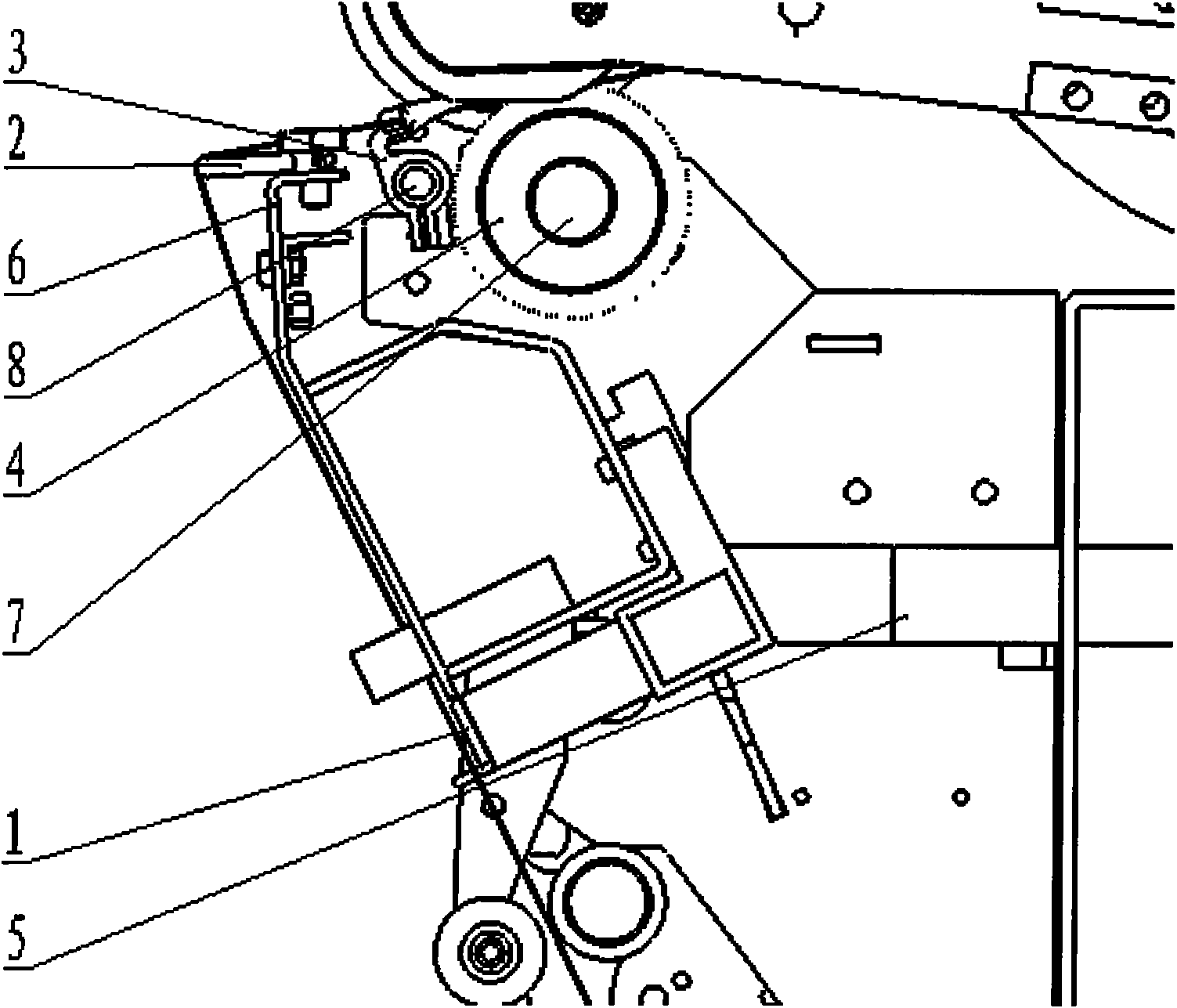
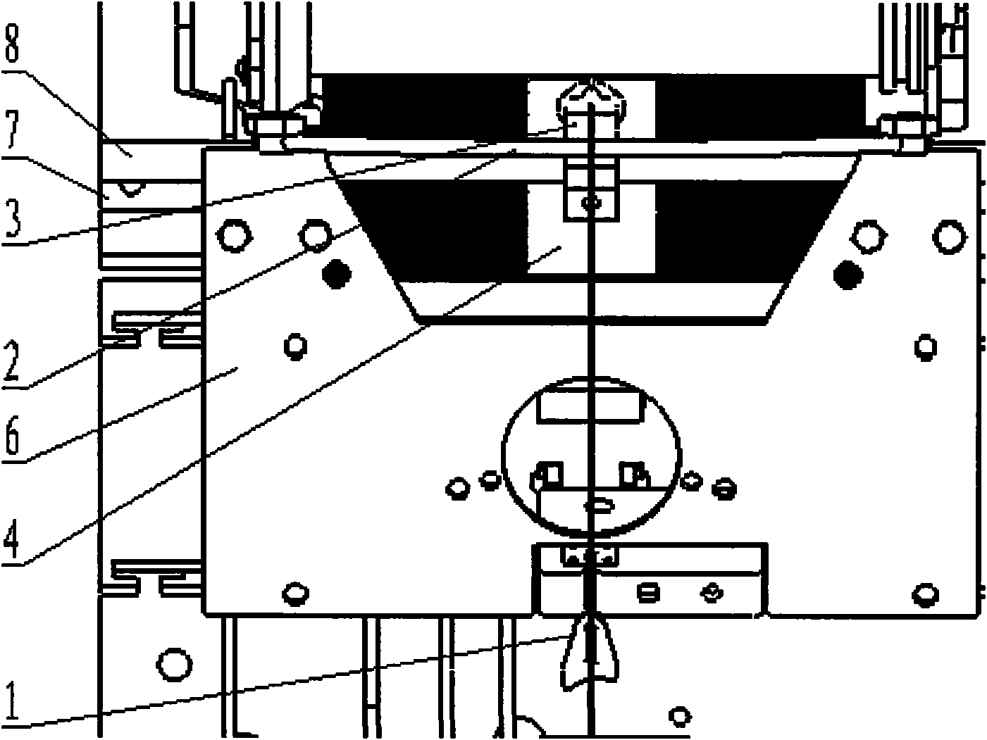
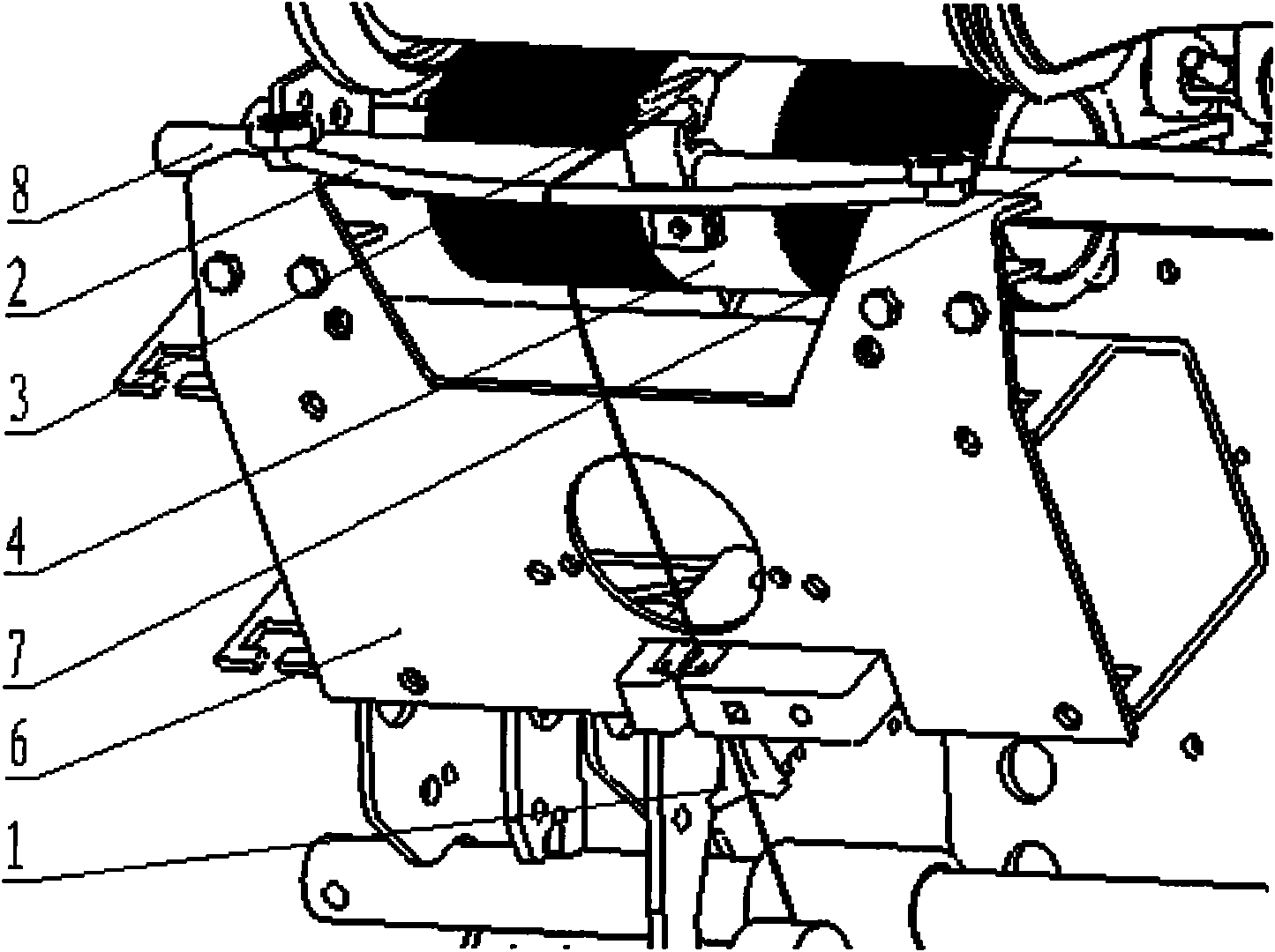
[0014] A constant tension device for a rotor spinning machine, which includes a yarn suction nozzle 1, an arc-shaped yarn guide rod 2, a yarn guide 3, a winding roller 4, a suction pipe 5, a panel 6, a winding roller shaft 7 and a horizontal The reciprocating rod 8 is connected to the yarn suction nozzle 1 and the suction pipe 5, and the suction pipe 5 is connected to the miscellaneous negative pressure channel; the curved yarn guide rod 2 is connected to the panel 6; the yarn guide 3 is connected to the traverse reciprocating rod 8 , The traversing reciprocating rod 8 is connected with the cam of the cam box; the winding roller 4 is connected with the winding roller shaft 7, and the winding roller shaft 7 is connected with the winding frequency conversion motor.

[0015] The radius of the arc yarn guide rod 2 is 175mm, and the chord length is 184mm.

[0016] The shape of the yarn suction nozzle 1 is that the front part is oblong, and the bottom of the mouth has ribs, one long...


PUM

PropertyMeasurementUnit
radiusaaaaaaaaaa
lengthaaaaaaaaaa

Abstract

The invention relates to a constant tension device of a rotor spinning machine, which comprises a yarn suction mouth (1), an arc-shaped yarn guide bar (2), a yarn guide (3), a winding roller (4), an air suction tube (5), a panel (6), a winding roller shaft (7) and a traverse reciprocating rod (8). The yarn suction mouth (1) is connected with the air suction tube (5), the air suction tube (5) is connected with an impurity-discharging negative-pressure channel; the arc-shaped yarn guide bar (2) is connected with the panel (6); the yarn guide (3) is connected with the traverse reciprocating rod (8), the traverse reciprocating rod (8) is connected with a cam of a cam case; the winding roller (4) is connected with the winding roller shaft (7), and the winding roller shaft (7) is connected with a winding variable frequency motor. The invention has a simple structure and a beautiful appearance, and can effectively solve the problem of yarn tension fluctuation of the rotor spinning machine, so that the yarn tension is constant, thereby ensuring that the yarn quality is consistent and stable and improving the rolling formation.

Description

technical field [0001] The invention belongs to a component of a textile machine, in particular to a constant tension device of a rotor spinning machine. Background technique [0002] There are many factors affecting the yarn tension of the rotor spinning machine, such as the difference between the winding speed and the drawing speed, the pressure of the creel, and the winding angle. In order to ensure the stable quality of the yarn and the formation of the package, the yarn is required to maintain a constant tension. [0003] The tension adjustment of the rotor spinning machine that is widely used at present is mainly to use the compensation bow to compensate the length of the yarn to ensure that the length of the yarn remains unchanged and does not affect the tension of the yarn. The periodically changing pulling force brought by the yarn has not been effectively controlled, so the pulling force acting on the yarn changes and fluctuates periodically. In addition, there is...

Claims


Application Information

Patent Timeline
Patent Type & Authority Applications(China)
IPC IPC(8): D01H4/08D01H13/10
CPCY02P70/62
Inventor 张新民闫进祥张耀民刘恒苏伟段建芳高原史文娟
Owner JINGWEI TEXTILE MASCH CO LTD
Why Eureka
Try Eureka