Buffer structure

A buffer structure and component technology, applied in coastline protection and other directions, can solve the problems of broken bridges, being washed away, and being easily damaged.

Inactive Publication Date: 2010-07-21
彭宇纶
View PDF0 Cites 3 Cited by
  • Summary
  • Abstract
  • Description
  • Claims
  • Application Information

AI Technical Summary

Problems solved by technology

[0002] By the way, when a typhoon or heavy rain strikes, a huge amount of rainfall often falls in a short period of time, causing the water volume of the river to increase and the water level to rise, so that the foundation piles of the bridges built on these rivers will be exposed or the riverbed around the embankment will be emptied. There have been accidents such as broken bridges, embankments, etc.
However, the various protection measures currently taken for the riverbed around the exposed bridge piers and embankments, such as placing wave-absorbing blocks, may still be washed away or easily damaged if the water flow is too large and rapid; Strong washing and impact of sand and gravel for a long time will often wear and break and cause continuous emptying; if all reinforced concrete is used for a long time, strong sand and gravel washing will also break through or damage, so despite the above measures, bridge breaks and collapses often occur dike events
[0003] The above-mentioned broken bridge crisis is caused by the exposed and emptied foundation piles of the bridge. The main reason for the exposed and emptied foundation piles is that the sand and gravel industry is mining sand and gravel in the upper reaches of the river, which makes the river unable to dispose of enough sand. The erosion of rocks to the middle and lower reaches makes the height of the middle and lower reaches of the riverbed continue to drop. Coupled with the long-term erosion of the river or the strong impact of the flood, the foundation piles of the bridge originally planted deeply under the riverbed are exposed or are washed away by the water. empty, thus forming a dangerous bridge with a crisis of broken bridge

Method used


Image

  • Buffer structure
  • Buffer structure
  • Buffer structure

Examples


Embodiment Construction

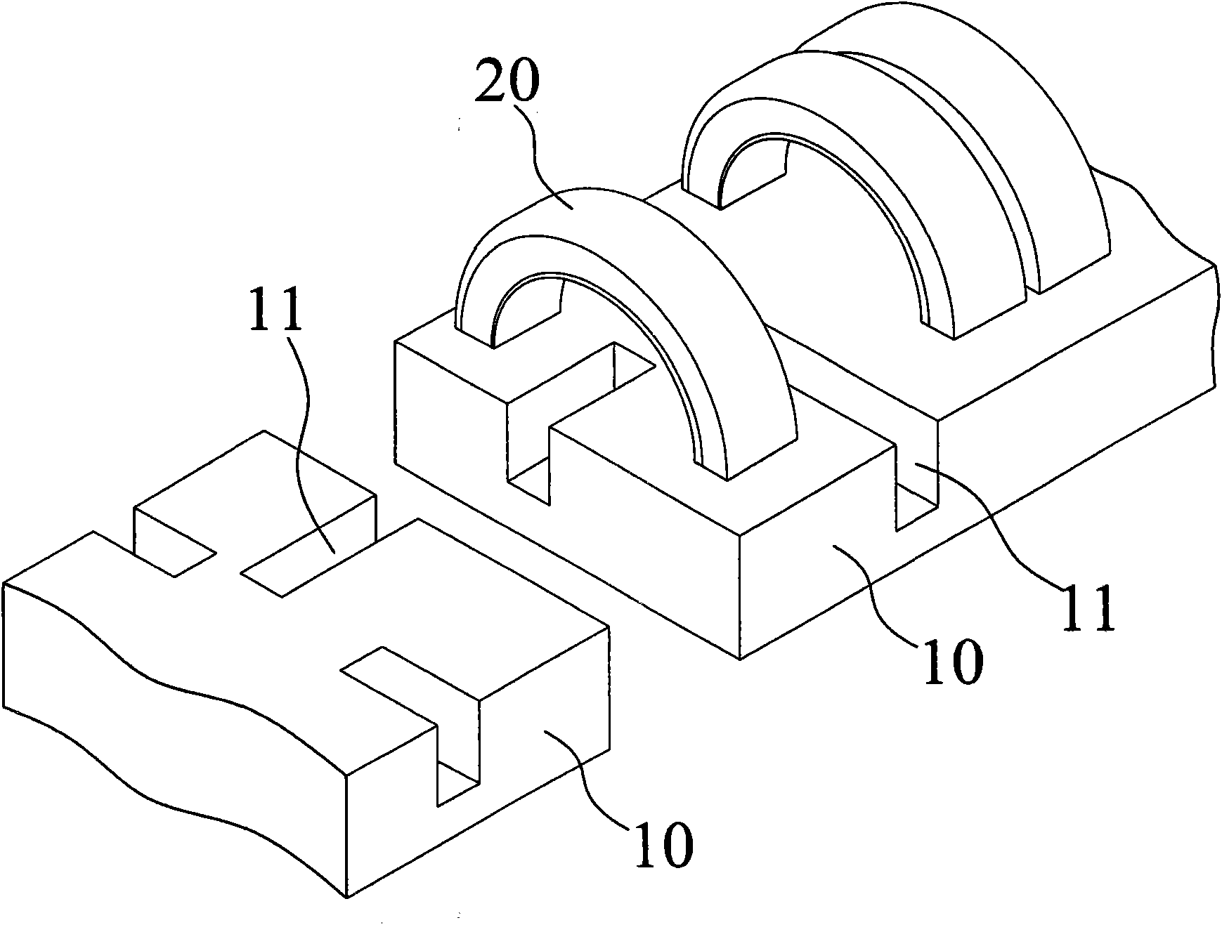
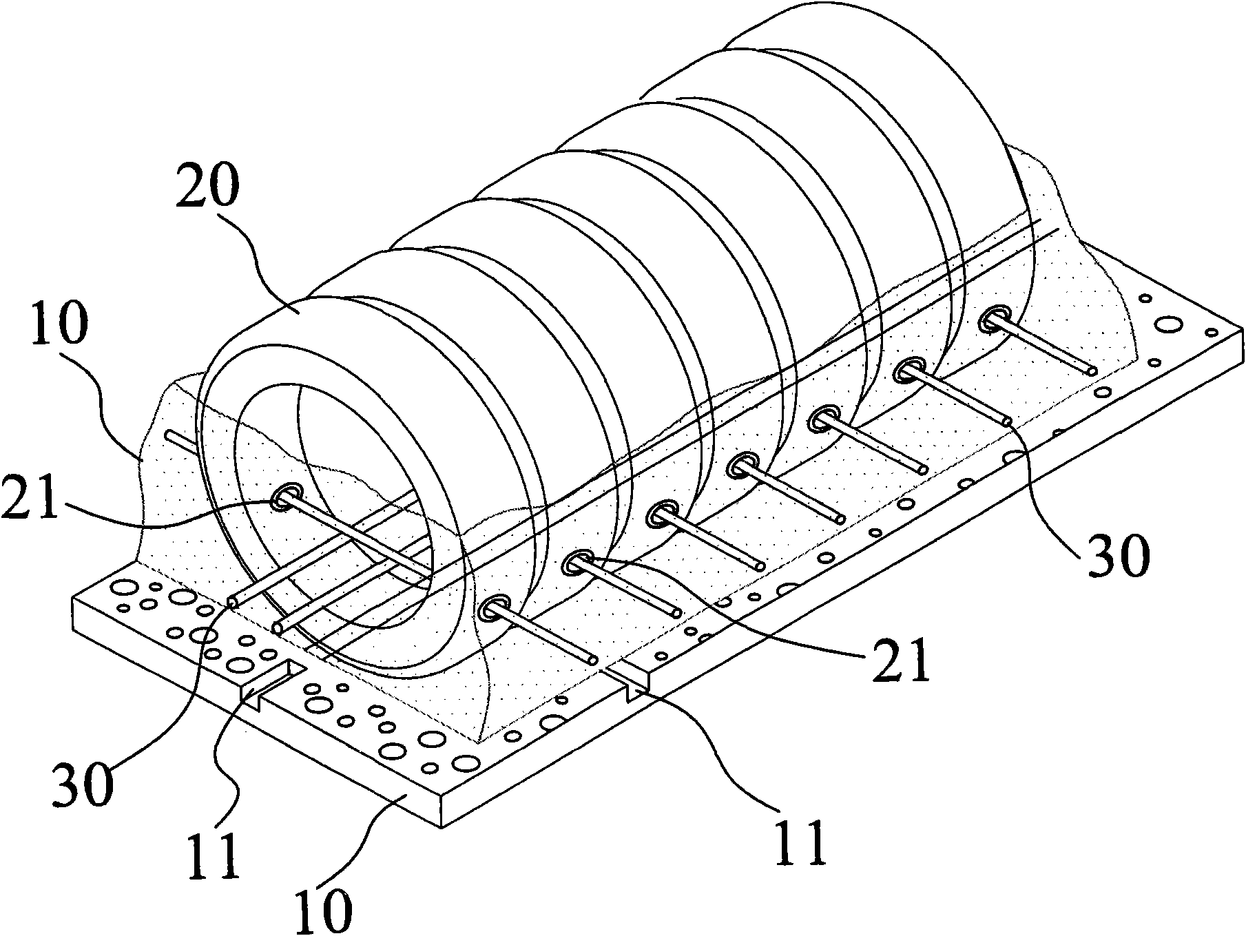
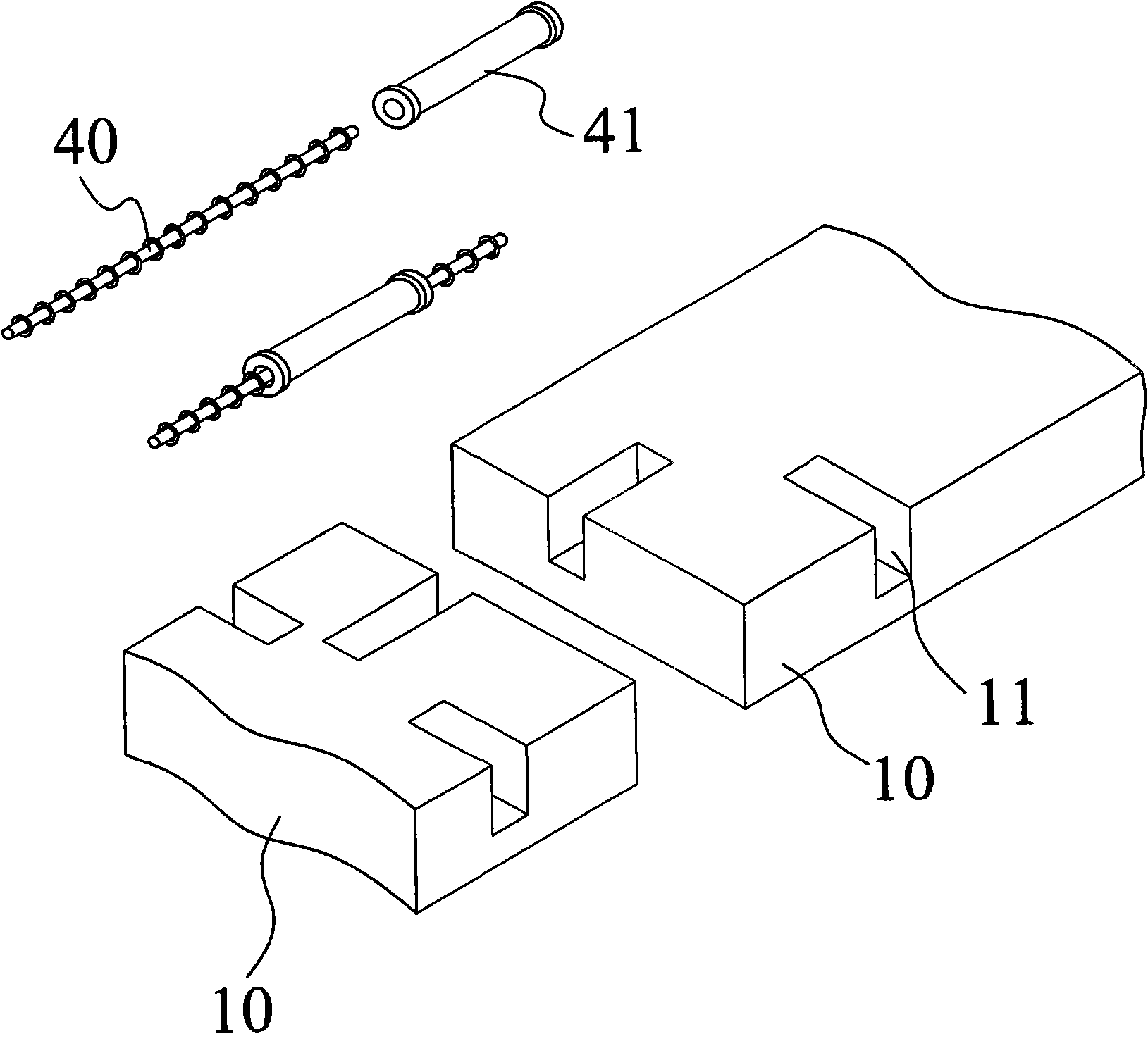
[0022] Please refer to Figures 1 and 2 together, which are perspective views of the structure of the present invention. The cushioning structure of the present invention includes a concrete base plate 10, the concrete base plate 10 is made of concrete material, in order to improve the wear resistance and impact resistance, the concrete base plate 10 is provided with at least one joint groove 11 on the opposite sides, and the concrete base plate 10 is provided with a buffer Components 20, wherein the cushioning components 20 can be elastically selected as single or plural quantities on the concrete substrate 10 according to the demand, and the cushioning components 20 can be rubber materials such as rubber plates or tires. In this implementation, the cushioning components 20 are in plural quantities The tire is vertically arranged on the concrete base plate 10 to illustrate an example; the buffer assembly 20 is provided with a fixed hole 21 opposite its periphery, and a pluralit...


PUM


Abstract

The invention relates to a buffer structure which comprises concrete substrates, wherein the periphery of each concrete substrate is respectively provided with at least one joint groove relatively; the concrete substrates are provided with a plurality of buffer components; the periphery of each buffer component is correspondingly provided with fixing holes, a plurality of first joint components and a plurality of second joint components; the first joint components penetrate through the fixing holes for connecting the buffer components in series; and the second joint components are embedded in the joint grooves to connect the plurality of concrete substrates with the same structure. The buffer structure is paved around a bridge or a dike of a river for buffering the impact of flood torrent by the buffer components in order to avoid scouring or caving the dike or the bridge of the river.

Description

technical field [0001] The invention relates to a buffer structure, in particular to an infrastructure suitable for preventing bridge piers from impacting or riverbeds around embankments being emptied by floods. Background technique [0002] By the way, when a typhoon or heavy rain strikes, a huge amount of rainfall often falls in a short period of time, causing the water volume of the river to increase and the water level to rise, so that the foundation piles of the bridges built on these rivers will be exposed or the riverbed around the embankment will be emptied. Accidents such as broken bridges and embankments have occurred. However, the various protection measures currently taken for the riverbed around the exposed bridge piers and embankments, such as placing wave-absorbing blocks, may still be washed away or easily damaged if the water flow is too large and rapid; Strong washing and impact of sand and gravel for a long time will often wear and break and cause continu...

Claims


Application Information

Patent Timeline
Patent Type & Authority Applications(China)
IPC IPC(8): E02B3/12
Inventor 彭宇纶
Owner 彭宇纶
Why Eureka
Try Eureka