
Scouring-resistant special high-pressure ceramic valve

A high-pressure ceramic and erosion-resistant technology, which is applied in the field of high-pressure ceramic valves, can solve problems such as prolonging the construction period, leakage of internal substances, and damage to the inner core of ceramic valves, and achieves the effects of weakening the erosion force, reducing wear, and making it easy to rotate

Inactive Publication Date: 2022-06-07
于骏
View PDF0 Cites 2 Cited by
  • Summary
  • Abstract
  • Description
  • Claims
  • Application Information

AI Technical Summary

Problems solved by technology

[0003] 1. The ceramic valves of the prior art are widely used in some high-pressure, high-wear and strong-corrosion environments. They are in harsh environments for a long time, and the internal high-speed liquid or high-pressure gas easily causes damage to the inner core of the ceramic valve, making it impossible to Normal work, in severe cases, cracks or ruptures in the ceramic valve, resulting in leakage of internal substances;
[0004] 2. Most of the ceramic valves in the prior art use bolts and other installation methods. The installation is slow and the operation process is complicated. For some frequently used parts, too much time is wasted in disassembly and assembly, which prolongs the construction period. The traditional connection There will also be leakage problems during the process, and the sealing is not strong

Method used


Image

  • Scouring-resistant special high-pressure ceramic valve
  • Scouring-resistant special high-pressure ceramic valve
  • Scouring-resistant special high-pressure ceramic valve

Examples


Embodiment 1

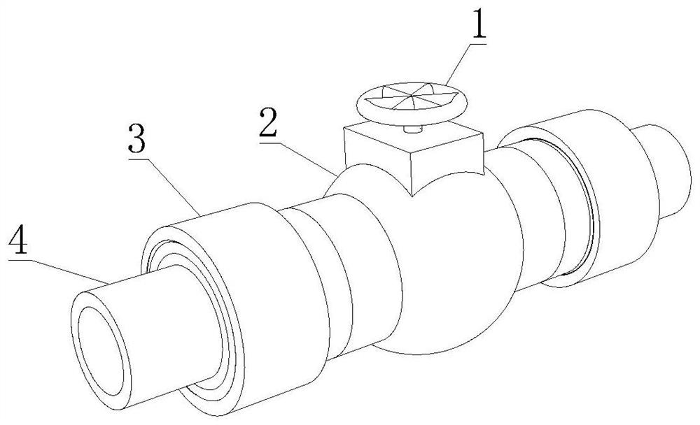
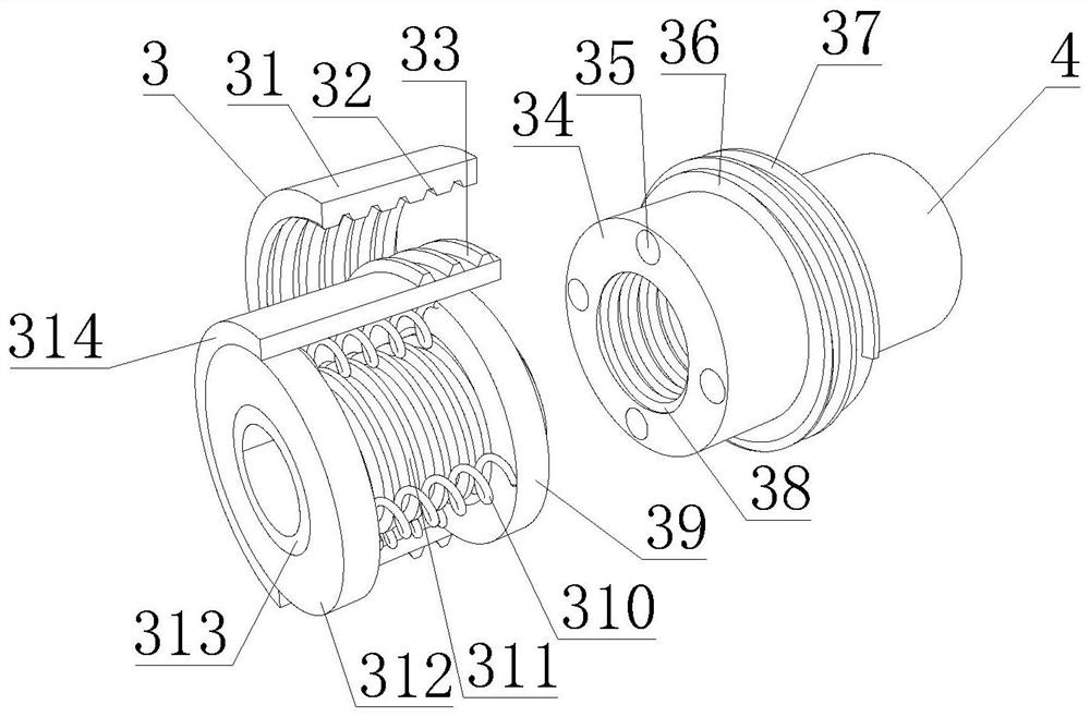
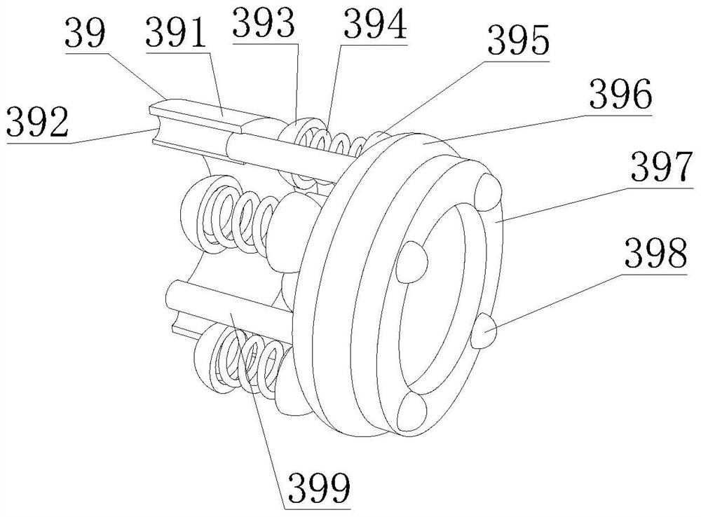
[0035] like Figure 1-6 As shown, the present invention provides a special high-pressure ceramic valve that is resistant to scouring, including a turntable 1, the lower end of the turntable 1 is fixedly connected with a scouring-resistant mechanism 2, and the scouring-resistant mechanism 2 includes a gradient ring 23 and a scouring wheel mechanism 26. The scouring wheel The mechanism 26 includes a wheel mechanism 261, and the wheel mechanism 261 includes a copper plate 2611. The outer side of the copper plate 2611 is provided with a guide groove 2613. One side of the erosion-resistant mechanism 2 is fixedly connected with a connecting mechanism 3, and the connecting mechanism 3 includes a sealing ring. The mechanism 39 and the inner tube 313. The sealing ring mechanism 39 includes a hard rubber ring 391. A circular hole 392 is opened inside the hard rubber ring 391. The outer surface of the inner tube 313 is fixedly connected with a threaded ring 311. An outer tube 4 is fixedl...

Embodiment 2

[0038] like Figure 1-6 As shown, on the basis of Embodiment 1, the present invention provides a technical solution: preferably, the outer side of the copper sheet 2611 is fixedly connected with a flow pipe 2612, the inner side of the copper sheet 2611 is fixedly connected with a hexagonal ring 2614, and the copper sheet 2611 is fixedly connected to the inner side. The inner side of the plate 2611 is fixedly connected with an elliptical ring 2615, the outer surface of the elliptical ring 2615 is fixedly connected with the outer surface of the hexagonal ring 2614, one side of the wheel mechanism 261 is fixedly connected with a connecting shaft sleeve 262, and the shaft of the connecting shaft sleeve 262 is fixedly connected. A rotating shaft 263 is fixedly connected to the center of the heart, and reinforcing particles 28 are rotatably connected to both ends of the rotating shaft 263 .

[0039] In this embodiment, through the internal high-speed and high-pressure material impac...

Embodiment 3

[0041] like Figure 1-6 As shown, on the basis of Embodiment 1, the present invention provides a technical solution: preferably, the outer side of the scouring wheel mechanism 26 is overlapped with a circular valve core 25, and the inner wall of the circular valve core 25 and the outer side of the reinforcing particles 28 are overlapped. Fixed connection, the inner wall of the circular valve core 25 is fixedly connected with a reinforcing rod 27, the outer side of the circular valve core 25 is rotatably connected with a valve casing 24, the side of the valve casing 24 is fixedly connected with a connecting pipe 21, and the inner wall of the connecting pipe 21 is fixedly connected There is a gradient plate 22, the other end of the gradient plate 22 is fixedly connected with a gradient ring 23, the upper side of the valve shell 24 is fixedly connected with a sealing seat 29, the upper side of the circular valve core 25 is fixedly connected with a connecting column 210, The outer...


PUM


Abstract

The invention discloses a washing-resistant special high-pressure ceramic valve, and relates to the technical field of high-pressure ceramic valves, the washing-resistant special high-pressure ceramic valve comprises a rotary table, the lower end of the rotary table is fixedly connected with a washing-resistant mechanism, the washing-resistant mechanism comprises a gradual change ring and a washing wheel mechanism, the washing wheel mechanism comprises a wheel sheet mechanism, the wheel sheet mechanism comprises a copper sheet plate, and the copper sheet plate is fixedly connected with the washing wheel mechanism. A connecting mechanism is fixedly connected to one side of the washing-resistant mechanism and comprises a sealing ring mechanism and an inner pipe. Internal high-speed and high-pressure substances impact the wheel sheet mechanism, the hexagonal ring, the oval ring and the two copper sheet plates form a basic frame, rotation is easier, after the high-speed and high-pressure substances enter the flow direction pipe and make contact with the guide groove, rotation of the wheel sheet mechanism is accelerated, the inner wall of the ceramic valve is prevented from being directly scoured, and the service life is prolonged. Centrifugal force generated by rotation of the wheel sheet mechanism, the connecting shaft sleeve and the rotating shaft further counteracts the scouring force, the problem that the scouring force of internal substances is too large is solved, and the effects of weakening the scouring force from multiple angles and improving the wear resistance of the ceramic valve are achieved.

Description

technical field [0001] The invention relates to the technical field of high-pressure ceramic valves, in particular to a special high-pressure ceramic valve that is resistant to erosion. Background technique [0002] Ceramic valve, using high-performance structural ceramics, it has good self-cleaning, super wear-resistant, strong corrosion, strong self-lubrication, long service life, wide use environment, especially suitable for use in chemical industry, in chemical industry, coal, petroleum In such harsh environments, metal valves can no longer meet the needs of harsh working conditions such as high wear and strong corrosion. It is mainly reflected in the situation that metal valves are easy to leak, have large torque, and the sealing surface is not resistant to corrosion. The application of ceramic materials to industrial valves is a A bold and useful innovation. The following problems exist for the prior art: [0003] 1. The ceramic valve of the prior art is widely used ...

Claims


Application Information

Patent Timeline
Patent Type & Authority Applications(China)
IPC IPC(8): F16K27/00
CPCF16K27/00Y02E10/20
Inventor 于骏
Owner 于骏
Learn More