Device for testing flow characteristics of gas-gas nozzle

A technology of flow characteristics and test equipment, applied in jet propulsion equipment, rocket engine equipment, machines/engines, etc., can solve the problems of affecting the flow of orifices, manpower, material resources, time loss, and high cost, and achieve stable and accurate feedback. environment, the design method is simple and effective, and the effect of saving manpower and material resources

Inactive Publication Date: 2010-07-21
BEIHANG UNIV
View PDF0 Cites 16 Cited by
  • Summary
  • Abstract
  • Description
  • Claims
  • Application Information

AI Technical Summary

Problems solved by technology

This kind of back pressure equipment has the following disadvantages for the test of nozzle flow characteristics: (1) The back pressure chamber is large in size and high in cost. (2) During the test process of measuring the flow coefficient of the nozzle, since the gas propellant ejected from the nozzle directly enters the anti-pressure chamber, if the volume of the anti-pressure chamber is too small, or the nozzle If the ejected flow rate is large, the pressure in the anti-pressure chamber will inevitably rise, which is higher than the design back pressure
[0006] It is known that the gas-gas nozzle ejects gas propellant, and the orifice has a throttling effect on the gas. When the pressure ratio before and after the orifice reaches a certain value, the airflow will reach the speed of sound at the minimum area of ​​the orifice. At this time, the flow rate through the orifice reaches the maximum value, and the external pressure disturbance wave propagating at the speed of sound cannot reach and pass through the orifice to affect the flow in the orifice.

Method used


Image

  • Device for testing flow characteristics of gas-gas nozzle
  • Device for testing flow characteristics of gas-gas nozzle
  • Device for testing flow characteristics of gas-gas nozzle

Examples


Embodiment Construction

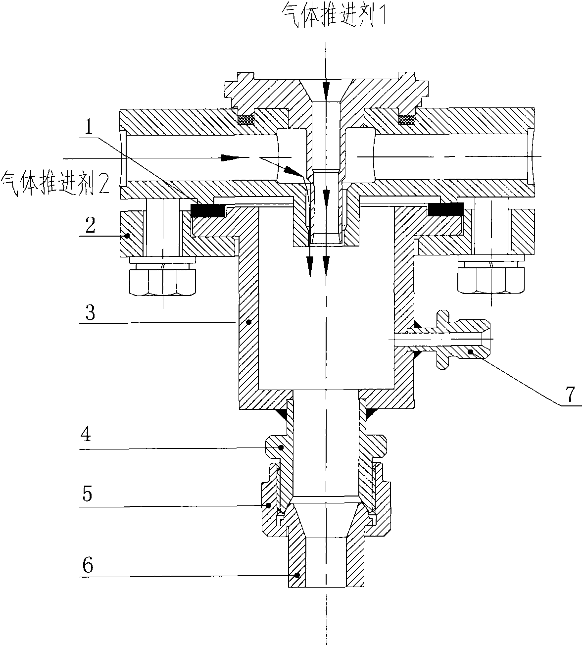
[0015] The invention proposes for the first time to use a throttling ball head with a throttling hole to throttle the gas propellant ejected from the gas-gas nozzle, so as to establish a back pressure environment for the flow characteristic test of the gas-gas nozzle. By replacing the throttling ball heads with different throttling apertures, any required pressure environment can be established for the gas-gas nozzle flow characteristic test, and the pressure environment is accurate and stable.

[0016] Such as figure 1 The air-air nozzle cold flow test device shown includes a gasket (1), a broken flange (2), a cavity (3), a nozzle (4) (7), an outer casing nut (5), a throttle ball head (6).

[0017] The design method of this test device is as follows:

[0018] 1. The propellant flow rate and propellant type through the gas-gas nozzle before the test are determined, defined as Its gas constant is known.

[0019] 2. The propellant is sprayed into the cavity through the air-...


PUM


Abstract

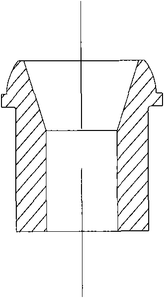
The invention discloses a device for testing flow characteristics of a gas-gas nozzle. The device uses a bulb throttling device to throttle a gaseous propellant jetted out by the gas-gas nozzle; when a throttling bulb reaches the sound velocity at the minimum cross section, an accurate and stable pressure environment can be established in a back pressure accommodating chamber; and by changing the bulb throttling device with different throttling pore diameters, a needed back pressure environment can be provided for a flow characteristic test of the gas-gas nozzle. The device comprises a sealing gasket (1), a fracture flange (2), an accommodating chamber (3), pressure inlets (4) and (7), a jacket nut (5) and the throttling bulb (6), wherein the pressure inlet (7) is used for mounting a pressure sensor; the pressure inlet (4) is matched with the jacket nut (5) to mounting the bulb throttling device (6); and the bulb throttling device can be changed automatically according to the back pressure environment needed to be established. The fracture flange is connected with the gas-gas nozzle through bolts, and the sealing gasket plays a role in sealing in the device. The fracture flange can solve mounting problems caused by the position of the pressure inlet (7), and simultaneously lightens the weight and reduces the cost, and different fracture flanges can be processed by aiming at flow characteristic tests of different gas-gas nozzles while other components such as the accommodating chamber are not needed to be processed again. The device for testing the flow characteristics of the gas-gas nozzle has the advantages of convenient use, low cost, small volume and light weight, overcomes the defects of a conventional back pressure cabin in the flow characteristic test of the gas-gas nozzle, and can provide an accurate and stable back pressure for the flow characteristic test of the gas-gas nozzle.

Description

【Technical field】 [0001] The invention is used to measure the flow characteristics of the air-air nozzle, and is a device that utilizes the propellant ejected from the air-air nozzle to build up pressure so as to provide back pressure for the nozzle cold flow test. It is mainly used in the experimental research on the flow characteristics of various nozzles where the propellant is gaseous. 【Background technique】 [0002] The nozzle is an important part of the liquid engine, and a kind of nozzle needs to be tested and researched on the flow characteristics of the nozzle before it is applied. The flow characteristic of the nozzle refers to the relationship between the nozzle pressure drop and the flow rate under certain back pressure conditions. The flow characteristic test is to measure the inlet pressure, back pressure and nozzle flow of the nozzle by means of the test, and determine the flow coefficient of the nozzle through the flow formula. The flow coefficient of the n...

Claims


Application Information

Patent Timeline
Patent Type & Authority Applications(China)
IPC IPC(8): F02K9/96
Inventor 蔡国飙高玉闪杜正刚
Owner BEIHANG UNIV
Why Eureka
Try Eureka