
Valve opening display and self-locking device used on rotary motion valve

A technology of valve opening display and self-locking device, applied in the direction of valve operation/release device, valve device, device to prevent accidental or unauthorized action, etc. It can not directly and accurately indicate the problems, so as to achieve the effect of simple maintenance, strong versatility and good economy.

Inactive Publication Date: 2012-05-30
李忠福
View PDF0 Cites 0 Cited by
  • Summary
  • Abstract
  • Description
  • Claims
  • Application Information

AI Technical Summary

Problems solved by technology

[0003] The purpose of the present invention is to solve the problem that the existing quarter-stroke valve with opening display function cannot directly and accurately indicate the real opening of the valve and does not have universality, and then provides a valve for quarter-stroke valves Opening display and self-locking device

Method used


Image

  • Valve opening display and self-locking device used on rotary motion valve
  • Valve opening display and self-locking device used on rotary motion valve
  • Valve opening display and self-locking device used on rotary motion valve

Examples


specific Embodiment approach 1

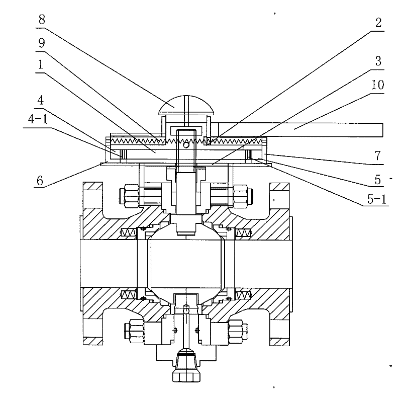
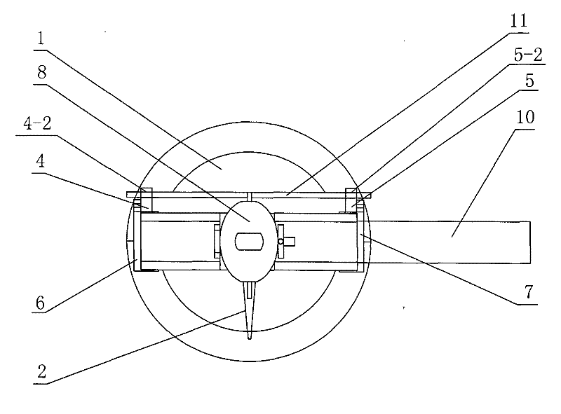
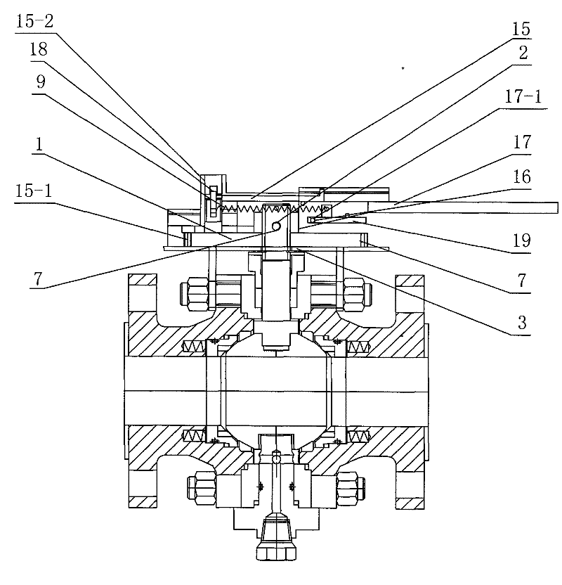
[0009] Specific implementation mode one: as Figure 1~2 As shown, the valve opening display and self-locking device of this embodiment consists of a large gear 1, a pointer 2, a supporting disc 3, a first lock head 4, a second lock head 5, a first limit block 6, a second lock head The limit block 7, the knob 8, the spring 9, the first wrench 10 and the push rod 11 are composed of the large gear 1 fixed on the upper end surface of the support disc 3, the first limit block 6 and the second The limit block 7 is symmetrically arranged on the support disc 3 with respect to the central axis of the support disc 3, and is located outside the large gear 1. The first lock head 4 is installed on the first limit block 6, so The second lock head 5 is installed on the second limit block 7, the first lock head 4 is processed with a plurality of first teeth 4-1, and the second lock head 5 is processed with a plurality of second teeth 5-1, and the first tooth 4-1 on the first lock head 4 and ...

specific Embodiment approach 2

[0010] Specific implementation mode two: as Figure 1~2 As shown, the number of the first teeth 4-1 in this embodiment is three to five. Other components and connections are the same as those in the first embodiment.

specific Embodiment approach 3

[0011] Specific implementation mode three: as Figure 1~2 As shown, the number of the second teeth 5-1 is three to five. Other components and connections are the same as those in the first embodiment.


PUM


Abstract

The invention relates to a valve opening display and self-locking device, in particular to a valve opening display and self-locking device used on a rotary motion valve. The invention solves the problems that the existing rotary motion valve with opening display function cannot directly and accurately indicate the true opening of the valve and the valve is not universal. A large gear is fixedly installed on the upper end surface of a bearing disc. The bottom end surface of the first limiting block and the bottom end surface of the second limiting block are relatively arranged on the bearing disc and are arranged on the two sides of the large gear. First teeth are arranged on a first locking head. Second teeth are arranged on a second locking head. The first teeth on the first locking headand the second teeth on the second locking head are engaged with the large gear. The lower end surface of a third limiting block is arranged on the bearing disc. Third teeth are arranged at the lowerpart of the third limiting block. The third teeth of the third limiting block are engaged with the large gear. The valve opening display and self-locking device can be installed on the supporting valve without changing the main body structure of the valve, the universality is high and the true opening of the valve is indicated.

Description

technical field [0001] The invention relates to a valve opening degree display and self-locking device, in particular to a valve opening degree display and self-locking device for angular stroke valves. Background technique [0002] At present, there are few valves with opening display function, and the existing angular stroke valves with opening display function can only indicate the stroke value of the valve core (rotated angle), and cannot directly and accurately indicate the real opening of the valve; The existing angular stroke valve opening degree display and self-locking device are integrated with the valve processing. Once the locking mechanism or the valve is damaged, it has to be discarded as a whole, which is not universal. Contents of the invention [0003] The purpose of the present invention is to solve the problem that the existing quarter-stroke valve with opening display function cannot directly and accurately indicate the real opening of the valve and doe...

Claims


Application Information

Patent Timeline
Patent Type & Authority Patents(China)
IPC IPC(8): F16K37/00F16K35/00F16K31/60
Inventor 李忠福赵长海程晓宇
Owner 李忠福
Learn More