Loop structure of bidirectional microchannel heat exchanger

A technology of microchannel heat exchanger and loop structure, which is applied in evaporator/condenser, lighting and heating equipment, refrigeration components, etc., to achieve the effect of lengthening refrigerant flow, sufficient heat exchange, and improved heat exchange performance

Active Publication Date: 2010-07-21
SANHUA HANGZHOU MICRO CHANNEL HEAT EXCHANGER +1
View PDF0 Cites 18 Cited by
  • Summary
  • Abstract
  • Description
  • Claims
  • Application Information

AI Technical Summary

Problems solved by technology

[0003] The object of the present invention is to provide a kind of loop structure of the two-way micro

Method used


Image

  • Loop structure of bidirectional microchannel heat exchanger
  • Loop structure of bidirectional microchannel heat exchanger
  • Loop structure of bidirectional microchannel heat exchanger

Examples


no. 1 approach

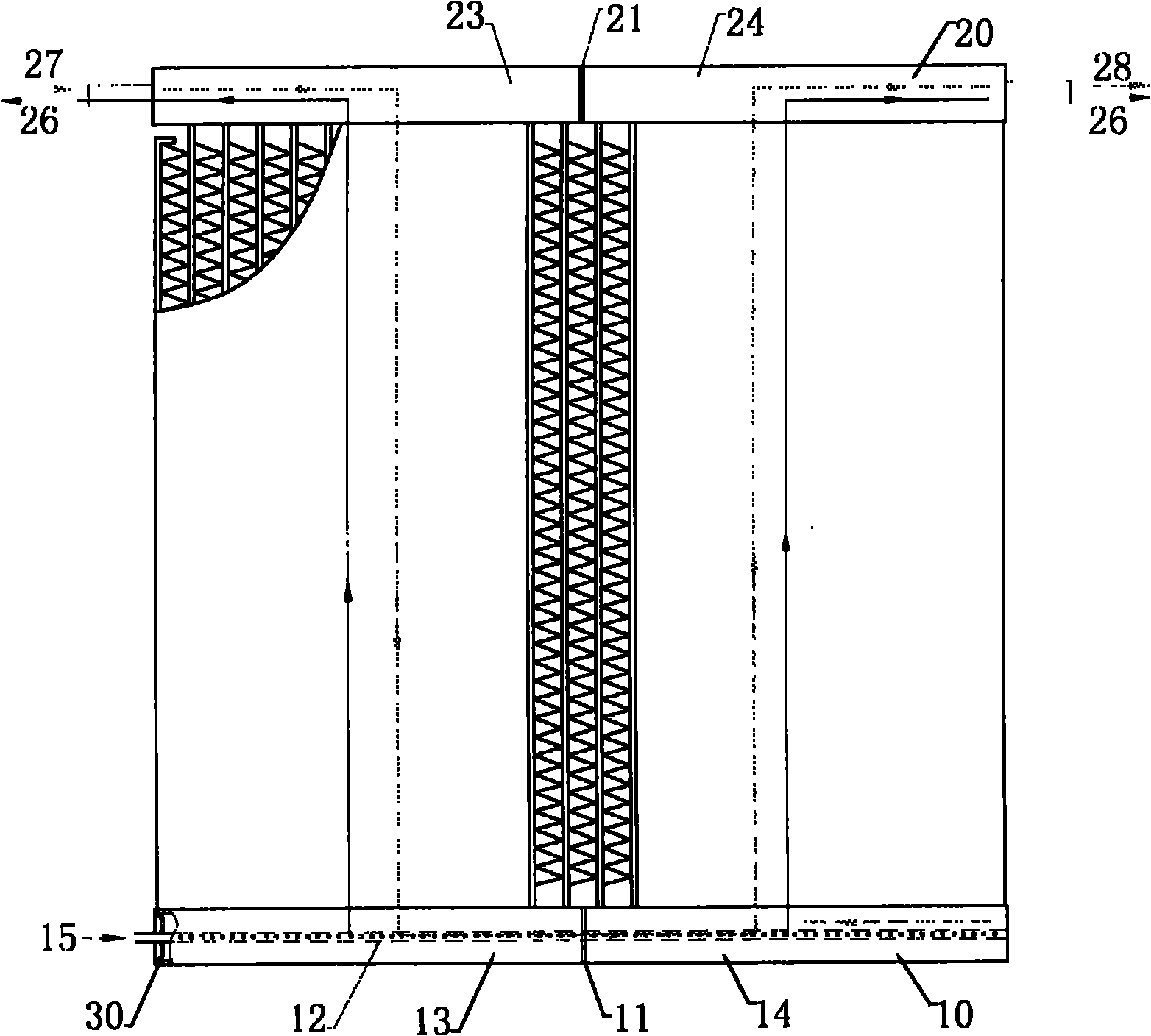
[0018] figure 1 is a schematic diagram of the loop structure of the bidirectional microchannel heat exchanger of the first embodiment.

[0019] Such as figure 1 As shown, the circuit structure of the bidirectional microchannel heat exchanger includes: a first header 10, a second header 20, a liquid separator 12, a separator 21, and a flat tube (not shown).

[0020] The first header 10 is provided with a plurality of flat tube slots, and the second header 20 is provided with flat tube slots corresponding to the number and positions of the flat tube slots on the first header 10, The parallel flat tubes are connected between the flat tube slots of the first header 10 and the flat tube slots of the second header 20 . The first collecting pipe 10 is provided with a liquid-distributing pipe 12, and a plurality of small holes are scattered on the liquid-distributing pipe 12. ) inner walls are welded together, and the other end runs through the left end cover 30 and extends to the ...

no. 2 approach

[0025] The basic structure of the circuit structure of the bidirectional microchannel heat exchanger of the second embodiment is the same as the basic structure of the circuit structure of the bidirectional microchannel heat exchanger of the first embodiment, and here, the same reference numerals are assigned to the same components.

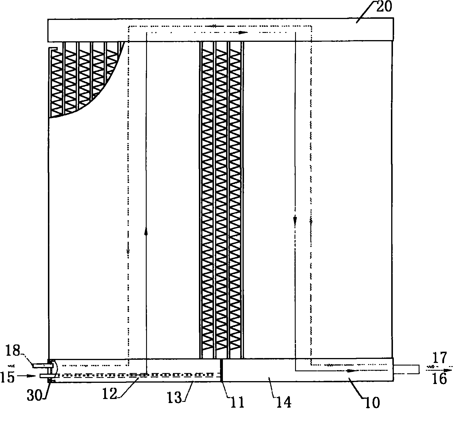
[0026] figure 2 It is a schematic diagram of the loop structure of the bidirectional microchannel heat exchanger of the second embodiment.

[0027] Such as figure 2 As shown, the circuit structure of the bidirectional microchannel heat exchanger includes: a first header 10, a second header 20, a liquid separator 12, a first partition 11, a second partition 21, flat tubes (figure omitted Show).

[0028] The first header 10 is provided with a plurality of flat tube slots, and the second header 20 is provided with flat tube slots corresponding to the number and positions of the flat tube slots on the first header 10, The parallel flat tubes are...

no. 3 approach

[0033] The basic structure of the circuit structure of the bidirectional microchannel heat exchanger of the third embodiment is the same as the basic structure of the circuit structure of the bidirectional microchannel heat exchanger of the first embodiment, and here, the same reference numerals are assigned to the same components.

[0034] image 3 It is a schematic diagram of the circuit structure of the bidirectional microchannel heat exchanger of the third embodiment.

[0035] Such as image 3 As shown, the circuit structure of the bidirectional microchannel heat exchanger includes: a first header 10, a second header 20, a liquid separator 12, a separator 11, and a flat tube (not shown).

[0036] The first header 10 is provided with a plurality of flat tube slots, and the second header 20 is provided with flat tube slots corresponding to the number and positions of the flat tube slots on the first header 10, The parallel flat tubes are connected between the flat tube slo...


PUM


Abstract

The invention provides a loop structure of a bidirectional microchannel heat exchanger, which comprises a first header pipe, a second header pipe, a shunt pipe, a diaphragm and flat pipes, wherein the first header pipe is provided with a flat pipe slot; the second header pipe is provided with a flat pipe slot, parallel flat pipes are connected between the flat pipe slot of the first header pipe and the flat pipe slot of the second header pipe; the first header pipe is provided with the shunt pipe; a plurality of small holes are distributed on the shunt pipe; one end of the shunt pipe is connected with the inner wall of a side end cap of the first header pipe and the other end of the shunt pipe passes through the other side end cap of the first header pipe to reach the outer side of the heat exchanger; the diaphragm is arranged in the second header pipe and divides the second header pipe into two cavities; a refrigerant heating inlet is arranged on the end part on the extended side of the shunt pipe; refrigerant heating outlets are arranged on two end parts of the two sides of the second header pipe; a refrigerant refrigerating inlet is arranged on any of the end parts on the two sides of the second header pipe; and a refrigerant refrigerating outlet is arranged on end part on the side, opposite to the side on which the refrigerant refrigerating inlet is arranged, of the second header pipe.

Description

technical field [0001] The invention relates to a loop structure of a bidirectional microchannel heat exchanger. Background technique [0002] When the micro-channel heat exchanger is used in the outdoor unit of the heat pump, the structure is simple and liquid separation is easy when a single circuit is used. However, due to the slow flow rate of the refrigerant, the heat transfer performance of the micro-channel heat exchanger cannot be fully utilized, so it is necessary to use two circuits or even more. loop to increase the flow rate of refrigerant and improve the heat transfer performance inside the heat exchanger, but the structure of two loops and multi-loop is more complicated than that of single loop, and there is a liquid separation problem between the loops. Contents of the invention [0003] The object of the present invention is to provide a circuit structure of a bidirectional microchannel heat exchanger which solves the problem of liquid separation in two cir...

Claims


Application Information

Patent Timeline
IPC IPC(8): F25B39/00
Inventor 刘华钊黄宁杰
Owner SANHUA HANGZHOU MICRO CHANNEL HEAT EXCHANGER
Why Eureka
Try Eureka