Electric precipitation device and scraping device

A technology of electric dust collection and dust collection, which is applied in the direction of electrostatic separation, electrode cleaning, external electrostatic separator, etc., can solve the problems of difficult-to-scratch performance, difficult-to-press margin, unstable dust stripping performance, etc., to achieve improved scraping performance effect

Inactive Publication Date: 2010-07-28
HITACHI PLANT TECH LTD
View PDF7 Cites 9 Cited by
  • Summary
  • Abstract
  • Description
  • Claims
  • Application Information

AI Technical Summary

Problems solved by technology

[0012] In the structure in which the fixed brush is pressed against the dust collecting electrode by its own weight, the brush is worn and the brush falls to the dust collecting electrode, so the contact angle changes, making the dust peeling performance unstable and it is difficult to grasp the correct scraping amount
In addition, in order to ensure the pressing force by the self-weight of the brush and the weight, the brush is used in an inclined state from the beginning, and it is difficult to ensure a large pressing margin ( The amount of movement to the dust collecting electrode), it is difficult to maintain uniform scraping performance for a long time
[0013] In Patent Document 1, in the case of a large-scale device, the number of moving electrodes becomes 50 to 100 channels, and since a driving device for driving them and a driving device for driving the rotation of the brush mechanism 40 are required, the equipment cost is huge, and the brush mechanism 40 needs to be driven. When worn, it is difficult to change the pressing margin of the brush mechanism due to the driving mechanism, and it is necessary to replace the brush mechanism in order to ensure the function, which requires cost and time
[0014] In Patent Document 2, since it is a fixed brush with bristles, sometimes the dust attached to the dust collecting electrode cannot be sufficiently scraped off by rotating in circles.

Method used


Image

  • Electric precipitation device and scraping device
  • Electric precipitation device and scraping device
  • Electric precipitation device and scraping device

Examples


Embodiment Construction

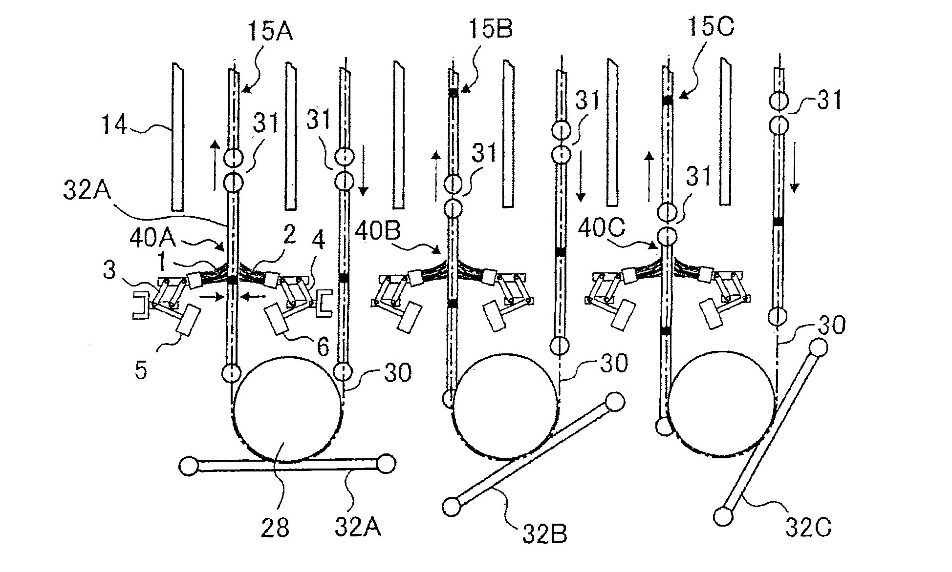
[0059] figure 1 It is a configuration diagram of the lower part of Embodiment 1 of the present invention. As the overall structure of the electrostatic precipitator and described in the above-mentioned background technology column Figure 9 ~ Figure 13 The ones shown are the same, and those given the same symbols as above represent the same elements.

[0060] figure 1 The moving electrodes 15A, 15B, and 15C arranged in the middle make the dust collecting pole plates 32A, 32B, and 32C, which are suspended on the endless chain 30 and descend in a circle, rotate at the position U of the lower roller 28 and change to rise. Scraping mechanisms (brush mechanisms) 40A, 40B, and 40C are respectively arranged at positions sandwiching both surfaces of the dust-collecting electrode plates 32A, 32B, and 32C that have just risen.

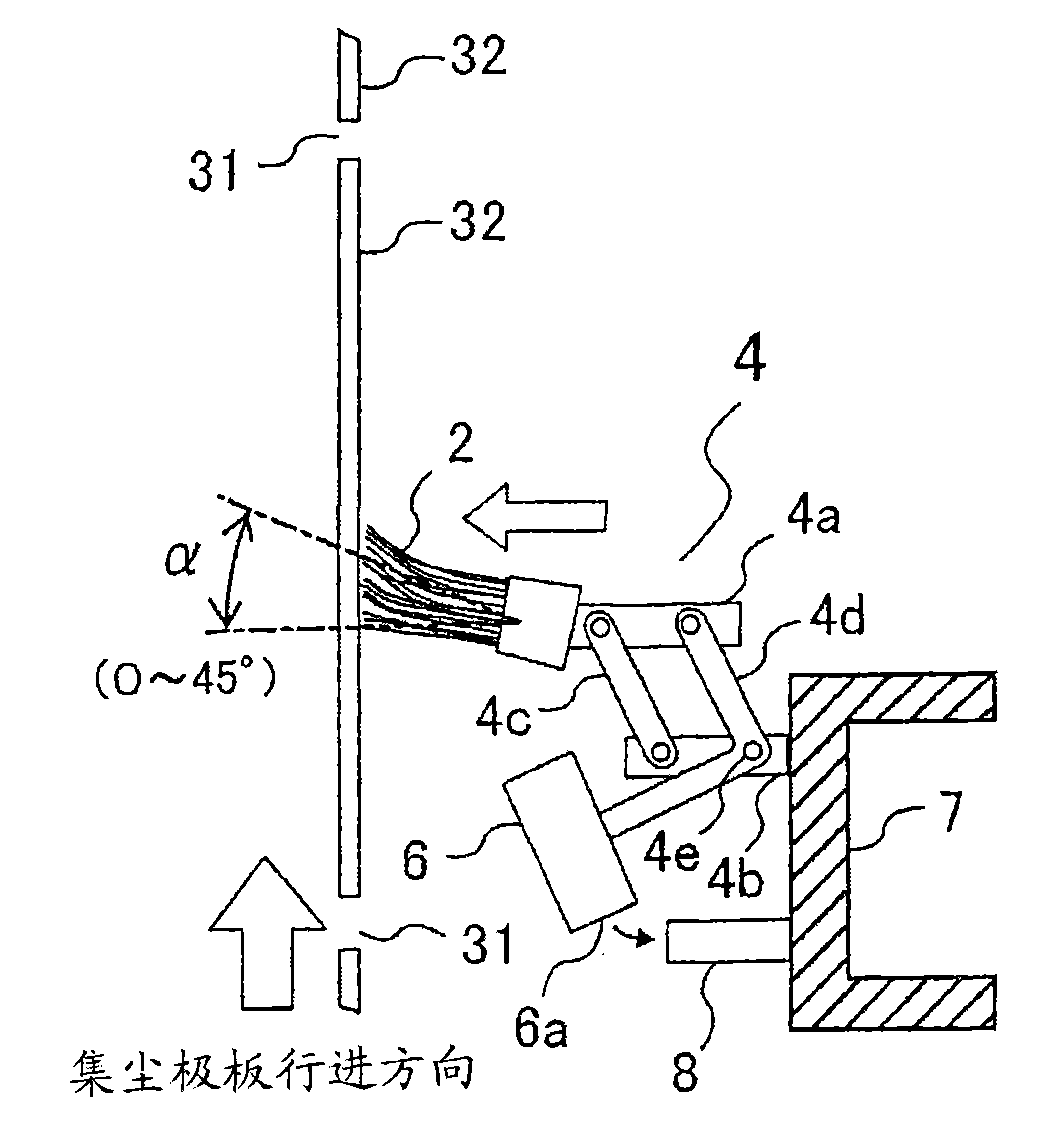
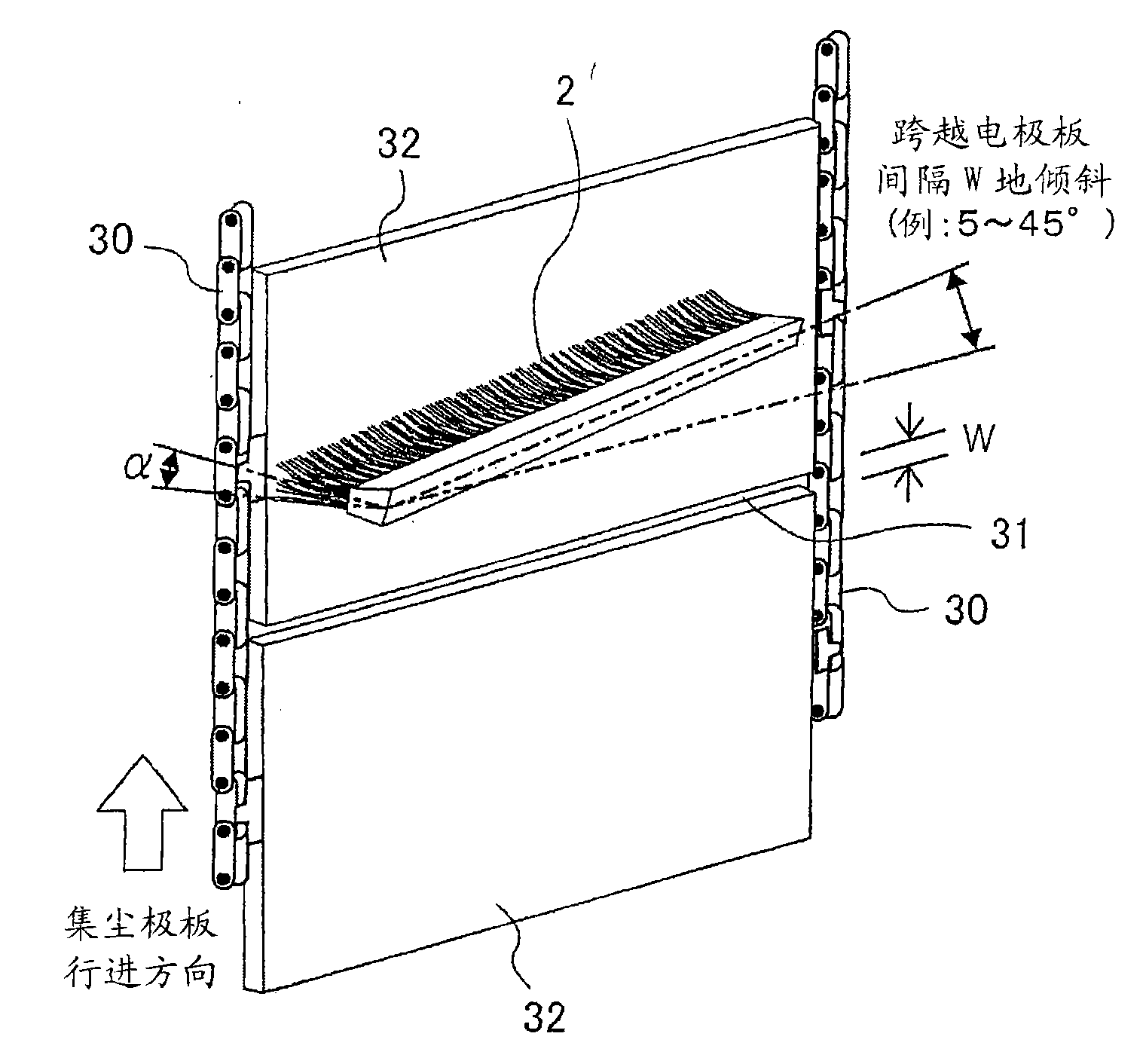
[0061] The brush mechanism 40A has: a pair of long brushes 1, 2 extending in the width direction and in contact with the surface of each dust-collecting pol...


PUM


Abstract

The invention provides an electric precipitation device and scraping device capable of reducing cost for scraping the dust and keeping the scraping performance for a long time. The movable electrode type electric precipitation device comprises a box for making the dirty gas flowing from a gas inlet to an outlet; a plurality of discharge electrodes suspended in a gas passage as the precipitation area in the box; a plurality of movable electrodes, wherein a plurality of precipitation electrode plates suspended on paired circular chains to form a loop and a rotary ring and a scraping mechanism scrapes the surface of the dust precipitation electrode plate of the rotary ring at the preset position. The scraping mechanism comprises: a long brush extending along the width direction and contacting with the surface of the precipitation electrode plate; a link mechanism with one end mounted on the brush and another end fixed by a fixing component; a force application mechanism for pushing the brush towards the precipitation electrode plate by the link mechanism and a limit mechanism for limit the movement of the brush to prevent the pushed brush embedded into the clearance between the adjacent two precipitation electrode plates.

Description

technical field [0001] The present invention relates to an electric dust collecting device and a scraping device having movable electrodes, and in particular to a device provided with a plurality of dust collecting electrodes suspended at predetermined intervals in a casing and arranged around these discharging electrodes to rotate in circles Electric dust collector and scraper. Background technique [0002] It is well known that such an electric precipitator is used, for example, as an electric precipitator for removing dust in the exhaust gas of a thermal power station boiler and various furnace exhaust gases for ironmaking, according to Figure 9 ~ Figure 13 A schematic configuration shown in Patent Document 1 will be described. [0003] Figure 9 Among them, the moving electrode type electric dust collecting device 10 includes: a box body 12, a funnel 13 at the lower part of the box body 12, a plurality of discharge frames (discharge electrodes) 14 and a plurality of mo...

Claims


Application Information

Patent Timeline
Patent Type & Authority Applications(China)
IPC IPC(8): B03C3/10B03C3/74
Inventor 安藤寻树白丸信彦望月美彦有光武雄早津昌树青山光太郎织田启吾
Owner HITACHI PLANT TECH LTD
Why Eureka
Try Eureka