Roll-up mechanism and offset printing press cylinder cleaner provided with same

A cleaning device and offset printing machine technology, applied to the general parts of printing machinery, printing, printing machines, etc., can solve the problems of high manufacturing cost, small contact area, high manufacturing cost, etc., and achieve the effect of easy manufacturing and simple mechanism structure

Inactive Publication Date: 2011-11-02
NINGBO JIUYUAN LUBRICATION EQUIP MFG
View PDF5 Cites 0 Cited by
  • Summary
  • Abstract
  • Description
  • Claims
  • Application Information

AI Technical Summary

Problems solved by technology

Although the above-mentioned patents ZL03808012.5 and ZL03808201.2 have solved this problem, the structural design is relatively troublesome, and the manufacturing cost is relatively high, so it is not easy to popularize; in addition, when cleaning the cleaning cloth, it needs to be compressed so that it can be cleaned Completely, the traditional hard material is used to press the cleaning cloth, which has a small contact area and has the disadvantage of poor cleaning effect. In addition, the hard material is easy to scratch the surface of the offset printing cylinder
For avoiding the unfavorable factor that hard material compresses clean wiping cloth to bring, someone proposes to replace with air bag, see the Chinese invention patent application publication " with constant contact area cleaning offset printing cylinder bag " (publication) that application number is 02829033.X No.: CN1628031A), the patent adopts the air bag, the cleaning area is increased, and it is in soft contact with the offset printing cylinder, which causes less damage to it, but the air bag has higher requirements for air pressure control, and the cleaning area cannot effectively ensure stability
In addition, this kind of airbag structure has relatively high manufacturing cost, and it is not easy to replace and maintain.

Method used


Image

  • Roll-up mechanism and offset printing press cylinder cleaner provided with same
  • Roll-up mechanism and offset printing press cylinder cleaner provided with same
  • Roll-up mechanism and offset printing press cylinder cleaner provided with same

Examples


Embodiment Construction

[0036] The present invention will be further described in detail below in conjunction with the accompanying drawings and embodiments.

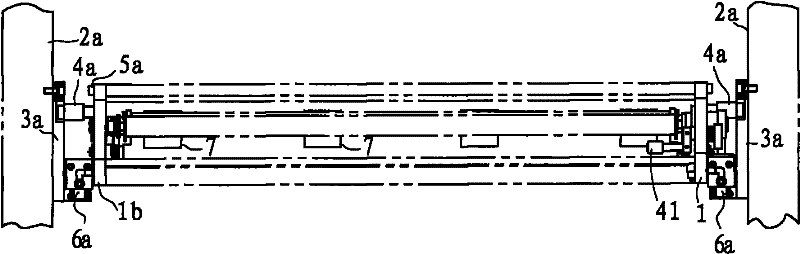
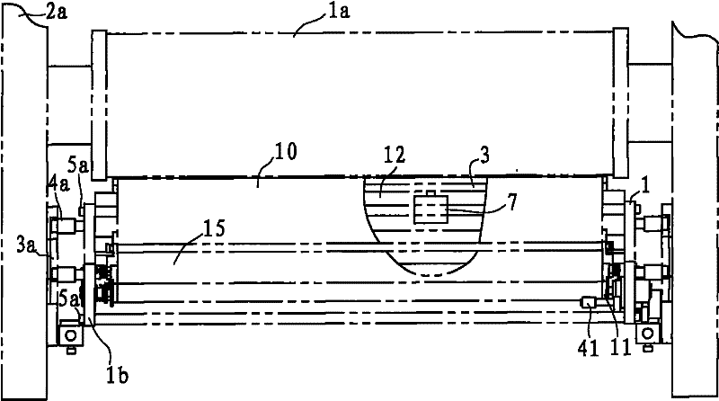
[0037] Such as figure 1 with figure 2 As shown, the cylinder surface cleaner of the offset printing machine in this embodiment is arranged on one side of the offset printing cylinder 1a, specifically as follows: machine wall panels 2a are provided on both sides of the offset printing cylinder 1a, and a fixed positioning plate is provided on the inner side of each machine wall panel 2a 3a, there are mounting plate 1 and mounting plate 1b on both sides of the cylinder surface cleaner of the offset printing machine. Both mounting plate 1 and mounting plate 1b are provided with two positioning pins 4a and one fixing pin 6a. The positioning pin 4a is embedded and fixed to the positioning plate 3a. Inside the positioning groove, the fixed pin 6a is inserted into the positioning pin hole of the fixed positioning plate 3a to realize the quick instal...


PUM


Abstract

A roll-up mechanism comprises mounting plates (1, 1b) and a reel (11) which can be rotatably arranged on the mounting plate (1) and is used for rolling up wiping rags (10). The mechanism is characterized by also comprising a pinch roller (41), a swing arm (2), a catch lever (4), a swing arm driver (5) and resetting pieces (21), wherein the pinch roller (41) presses the wiping rags (10) on the reel (11) tightly; the first end of the swing arm (2) is connected with the reel (11) and can drive the reel (11) to rotate in the single direction after being stressed, and the second end of the swing arm (2) is provided with a first stressed portion (22) and a second stressed portion (23); the catch lever (4) always acts on the first stressed portion (22) and is connected with the pinch roller (41)and coaxially rotates with the pinch roller (41); and the swing arm driver (5) is provided with a power output end (51) acting on the second stressed portion. The invention also discloses an offset printing press cylinder cleaner provided with the roll-up mechanism. Compared with the prior art, the invention has the following advantages: the whole mechanism is simple in structure, easy to manufacture, convenient to use after being mounted on the existing offset printing presses and has high cleaning efficiency and low cost.

Description

technical field [0001] The invention relates to a cloth rolling mechanism, in particular to a cloth rolling mechanism applied to a cylinder cleaner of an offset printing machine, and the application also relates to a cylinder cleaning device of an offset printing machine equipped with the cloth rolling mechanism. Background technique [0002] Existing offset printing machine after working for a certain period of time, the cylindrical surface of offset printing cylinder, embossing cylinder, printing plate cylinder on the offset printing machine just needs cleaning. The traditional cleaning method is to manually wipe the surface of the drum with a cloth soaked in cleaning liquid. Since the operating space is very narrow, and at the same time the machine needs to be jogged to rotate the drum while scrubbing, the work efficiency is very low, and the cleaning effect depends entirely on the cleaning effect. on the skills of the operator. And it's not safe. [0003] For this reas...

Claims


Application Information

Patent Timeline
Patent Type & Authority Patents(China)
IPC IPC(8): B41F35/06
Inventor 许永久
Owner NINGBO JIUYUAN LUBRICATION EQUIP MFG
Why Eureka
Try Eureka