Curved variable torque shift disc, shift mechanism and agricultural machinery

A shifting mechanism and shifting disc technology, applied in the direction of mechanical equipment, components with teeth, transmission device control, etc., can solve the problems of difficult to shift to the required gear, inconvenient shifting, and difficulty in shifting, etc. Achieve the effects of avoiding jumping gears, high gear shifting precision, and stable rotation

Active Publication Date: 2019-02-15
LONCIN MOTOR
View PDF5 Cites 0 Cited by
  • Summary
  • Abstract
  • Description
  • Claims
  • Application Information

AI Technical Summary

Problems solved by technology

The existing shift mechanism usually includes a joystick, a shift arm and a cable. The joystick, the shift arm and the cable are connected by a parallelogram principle. The rotation of the gear arm, when the moment arm of the shift arm becomes smaller, the moment arm of the operator to push (pull) the shift lever also becomes smaller, so that the force that the operator needs to apply is multiplied; when the moment arm of the shift arm becomes When it is large, the moment arm of the operator to push (pull) the shift lever will also increase correspondingly, so that the force that the operator needs to apply will be doubled and smaller, resulting in inconvenient shifting. In order to reduce the influence of the change of the moment arm of the shift arm, There is a disc-shaped equimoment arm shift disc, the cable is wound around the shift disc and the arm of the shift disc remains unchanged during the rotation process, but the change of the lever arm still requires the operator to apply force on the hand. The force changes constantly, making it difficult to change gears, and it is not easy to shift to the desired gear.

Method used


Image

  • Curved variable torque shift disc, shift mechanism and agricultural machinery
  • Curved variable torque shift disc, shift mechanism and agricultural machinery

Examples


Embodiment Construction

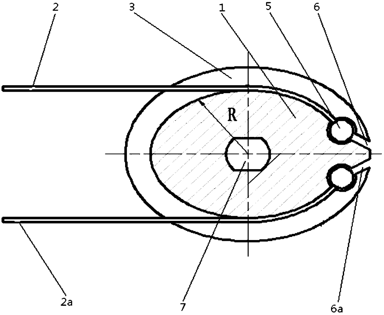
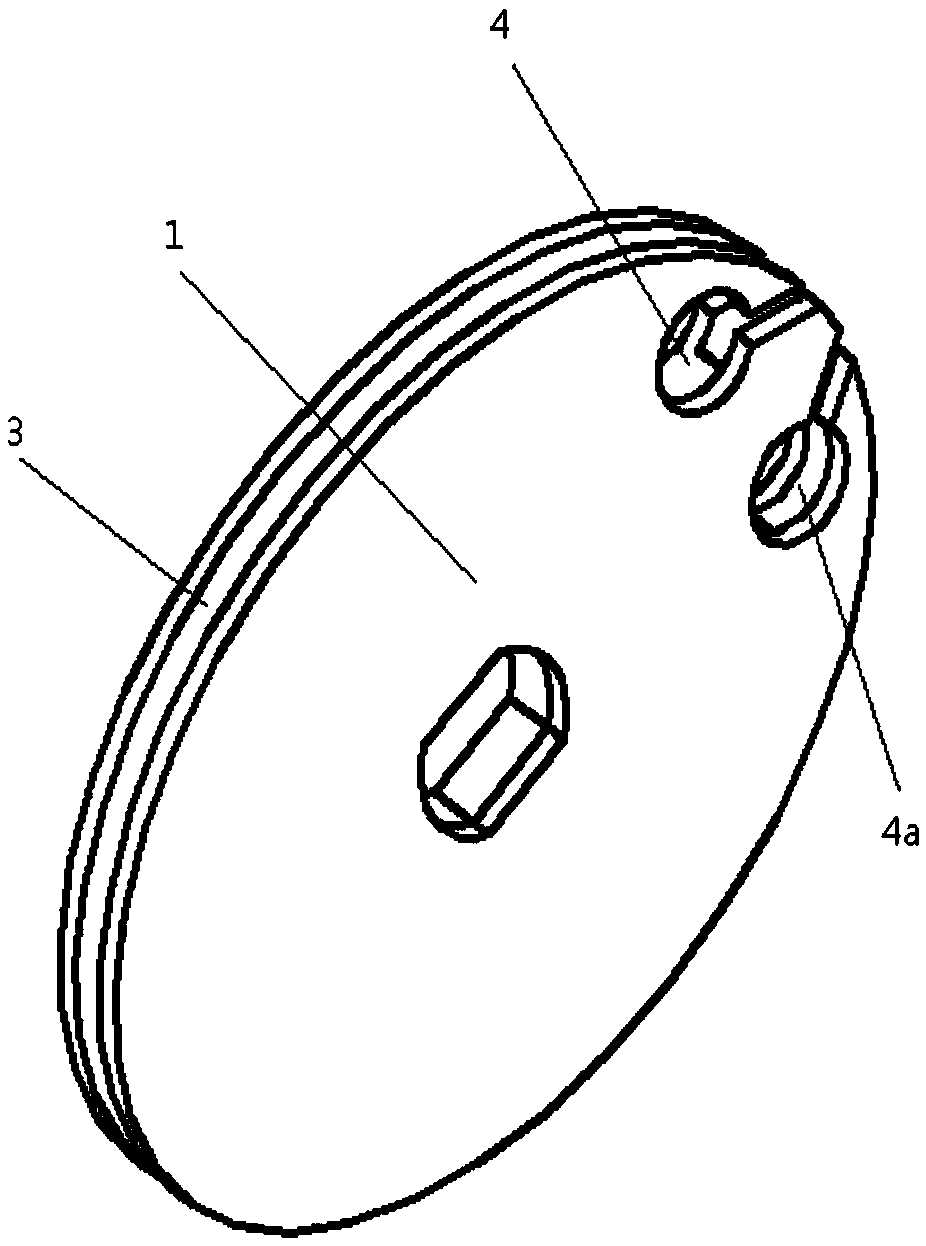
[0019] figure 1 It is a structural schematic diagram after the dragline is installed in the present invention, figure 2 It is a schematic diagram of the structure of the present invention without the installation of the cable. As shown in the figure, this embodiment discloses a curve-variable torque shift disc. The shift disc 1 and the shift shaft are fixed along the circumferential direction and are used to drive the shift The shaft rotates, the end of the cable 2 is fixed on the edge of the shifting disc 1 and the cable 2 wraps around a part of the edge of the shifting disc 1. The shifting disc 1 is a non-circular disc; The side wall of the gear plate body along the circumferential direction, the edge line of the shifting plate 1 is a non-circular line, of course, the edge line of the shifting plate can be set as a curve according to actual needs, and the curve is conducive to effective control of the driving force arm And adjust, so that the moment arm of the shifting dis...


PUM


Abstract

The invention discloses a curve changeable torque shifting reel, a shifting mechanism and a farm machine. The shifting reel is fixed to a shifting shaft in the circumferential direction and used for driving the shifting shaft to rotate, the end portions of inhaul cables are fixed to the edge of the shifting reel, the inhaul cables are wound on the partial edge of the shifting reel, and the shifting reel is a non-circular reel; design of the shape of the shifting reel facilitates effective control and adjusting to a driving moment arms, so that the moment arm of the shifting reel is opposite to the moment arm of a shifting lever in change, namely, the moment arm of the shifting reel becomes longer while the moment arm of the shifting lever becomes shorter, the moment arm of the shifting reel becomes shorter correspondingly while the moment arm of the shifting lever becomes longer, and stabilization of force driving the shifting lever is guaranteed; design of the shape of the shifting reel enables control over the driving moment arms to be more effective, so that shifting is more steady; moreover, the curve changeable torque shifting reel is simple and compact in structure, convenient to mount, and low in cost; and a driven arm rotates steadily after being driven, the shifting accuracy is high, and the problems that trip stop happens or a gear cannot be engaged are avoided.

Description

technical field [0001] The invention relates to the field of agricultural machinery, in particular to a curve variable torque shift disc, a shift mechanism and agricultural machinery. Background technique [0002] The shifting mechanism is an indispensable and important part of agricultural machinery (such as a tiller), which is used to connect the shifting mechanism and the shift shaft on the transmission to realize the shifting operation of the agricultural machinery. The existing shift mechanism usually includes a joystick, a shift arm and a cable. The joystick, the shift arm and the cable are connected by a parallelogram principle. The rotation of the gear arm, when the moment arm of the shift arm becomes smaller, the moment arm of the operator to push (pull) the shift lever also becomes smaller, so that the force that the operator needs to apply is multiplied; when the moment arm of the shift arm becomes When it is large, the moment arm of the operator to push (pull) t...

Claims


Application Information

Patent Timeline
Patent Type & Authority Patents(China)
IPC IPC(8): F16H59/02
CPCF16H59/02
Inventor 蔡晓勇喻诗品李家荣
Owner LONCIN MOTOR
Why Eureka
Try Eureka