Automatic roll stamping seal device

A rolling printing and stamping technology, applied in the field of automatic rolling stamping and stamping devices, can solve the problems of increasing the mechanism, increasing the cost, and having problems, and achieving the effect of precise control of the position

Active Publication Date: 2010-07-28
CHENGDU JIAYITONG INFORMATION TECH CO LTD
View PDF1 Cites 21 Cited by
  • Summary
  • Abstract
  • Description
  • Claims
  • Application Information

AI Technical Summary

Problems solved by technology

For the clutch control method, since the clutch is connected with the motor through gears and driven by the motor, in this control structure, the two elements that affect its service life are the motor and the clutch, which increases the probability of mechanism failure (that is, any of them If there is a problem with a component, there will be a problem with the mechanism), and the price of the clutch is not very low, which increases the cost; for the detection method of the rolling position of the rolling stamp, the realization method is when the rolling stamp rolls a week (360 degrees) Finally, the notch of the turntable is facing the groove sensor, so as to get the signal and feed it back to the control system. This method has a defect, that is, when the stamp is rotating, but it does not complete a circle, the device suddenly encounters an unexpected power failure. After powering on for the first time, the system cannot obtain the exact position of the stamp, so it cannot judge whether it is necessary to turn the stamp shaft in the positive direction or in the opposite direction to return the stamp rotation position to the initial position. Contact at any time, if no paper passes through the paper feeding channel, and the stamp is controlled to rotate in a random direction, it may cause the ink to attach to the output transfer roller during the contact process between the stamp and the output transfer roller, causing damage to the paper that enters later. Pollution; for the use of mechanical damping parts, since the damping part is used as a spherical body, under the action of the compression spring, it is elastically and periodically embedded in contact with the slot hole of the damping part installed on the shaft of the seal. Finally, the spherical body is embedded in the slot to prevent the rotating shaft from rotating. One disadvantage of this method is that the damping part on the rotating shaft is always in contact with the spherical body during the rotation process, and the wear is large. Even if it is used very durable The grinding material itself still has a limited service life, which increases the probability of failure of mechanical parts

Method used


Image

  • Automatic roll stamping seal device
  • Automatic roll stamping seal device
  • Automatic roll stamping seal device

Examples


Embodiment Construction

[0016] The present invention will be further described below in conjunction with the accompanying drawings.

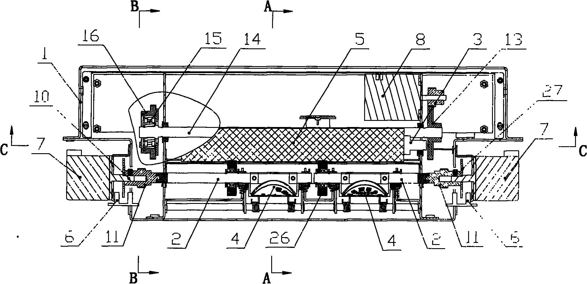
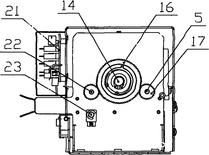
[0017] Such as Figure 1 to Figure 4 As shown, the automatic roll printing and stamping device of the present invention includes a paper feed channel, a seal rotating shaft 2 and a roll printing rotating shaft 3 arranged on the frame 1 on both sides of the paper feeding channel, and a rolling stamp 4 is arranged on the seal rotating shaft 2, Rolling printing rotating shaft 3 is provided with the rolling printing roller 5 that is arranged correspondingly with rolling stamp 4, and seal rotating shaft 2 and rolling printing rotating shaft 3 transmissions are connected with drive motor, and position sensor 6 is arranged on the frame 1 next to rolling stamp 4, in An encoder 7 is transmission-connected on the seal rotating shaft 6 . Such as figure 2 As shown, the paper feed channel is formed by the combination of the lower paper guide plate 19 and the upper paper guide pl...


PUM


Abstract

The invention discloses an automatic roll stamping seal device which can accurately detect the rotating position of a rolling seal; the automatic roll stamping seal device comprises a paper feed channel, a seal rotating shaft and a roll stamping rotating shaft which are arranged at two sides of the paper inlet channel, a rolling seal is arranged on the seal rotating shaft, a roll stamping roll which is arranged corresponding to the rolling seal is arranged on the roll stamping rotating shaft, the seal rotating shaft and the roll stamping rotating shaft are connected with a drive motor in a transmitting way, a position sensor is arranged on the rack beside the rolling seal, and an encoder is connected with the seal rotating shaft; all around monitoring can be carried out within 360-degree range of the seal rotating shaft, and the control position is more accurate; in addition, the position of the rolling seal can be accurately tracked owning to the arrangement of the encoder; a mechanical damping part in the background technology can be cancelled, the rotation and halt of the rolling seal can be accurately controlled by a motor, so as to improve the control reliability and reduce the effectiveness lose odds of the rotation and halt of the rolling seal; the device is particularly suitable for being popularized and applied to the automatic seal device.

Description

technical field [0001] The invention relates to a stamping device, in particular to an automatic rolling seal stamping device. Background technique [0002] At present, many batch bills that need to be stamped are processed in batches first, and then manually stamped one by one after checking. With the development of self-service equipment nowadays, there have been some service terminals that provide self-service printing of bills, but this kind of bills that are automatically printed are not stamped with the official seal of the service unit, and customers cannot obtain legal certificates, so customers who need stamping Still have to go to the counter for processing, not reaching the purpose of complete self-help. At the same time, there are already similar stamping devices, such as the patent application with application number 200720107842.2, which involves the use of clutches, the use of clutches, the use of rotary discs and groove sensors to detect the rolling position...

Claims


Application Information

Patent Timeline
Patent Type & Authority Applications(China)
IPC IPC(8): B41K3/00B41K3/62B41K3/48B41K3/54
Inventor 谢万彬李晓波罗明元陈洪恩马宗涛
Owner CHENGDU JIAYITONG INFORMATION TECH CO LTD
Why Eureka
Try Eureka