
Train temporary speed-limiting method based on self-organizing network

A technology of self-organizing network and temporary speed limit, applied in network topology, railway car body parts, vehicle route interaction equipment, etc., can solve problems such as endangering driving safety, increasing manual inspection workload, and slow accidents, etc. Improve traffic safety, realize train speed limit automation, and reduce workload

Inactive Publication Date: 2010-07-28
SOUTH CHINA UNIV OF TECH
View PDF1 Cites 13 Cited by
  • Summary
  • Abstract
  • Description
  • Claims
  • Application Information

AI Technical Summary

Problems solved by technology

[0004] Yet the above-mentioned two kinds of technical schemes of temporary speed limit also have the following deficiencies: 1. During temporary speed limit, temporary speed limit device or radio frequency card need to be artificially laid along the railway line, and this mode is relatively slow for the response of sudden accident, has The problem that the temporary speed limit device or radio frequency card cannot be arranged in time causes the speed limit information to be read in time, thus endangering driving safety; 2. After the temporary speed limit device or radio frequency card is laid, it is necessary to check its working condition frequently to prevent temporary The speed limit device or radio frequency card is damaged or stolen, which increases the workload of manual inspection, and may fail to find that the temporary speed limit device or radio frequency card is damaged or lost due to personnel negligence, so that the speed limit information is generated during the temporary speed limit Read failure, prone to safety accidents;

Method used


Image

  • Train temporary speed-limiting method based on self-organizing network
  • Train temporary speed-limiting method based on self-organizing network
  • Train temporary speed-limiting method based on self-organizing network

Examples


Embodiment Construction

[0049] The present invention will be described in further detail below in conjunction with the embodiments and the accompanying drawings, but the embodiments of the present invention are not limited thereto.

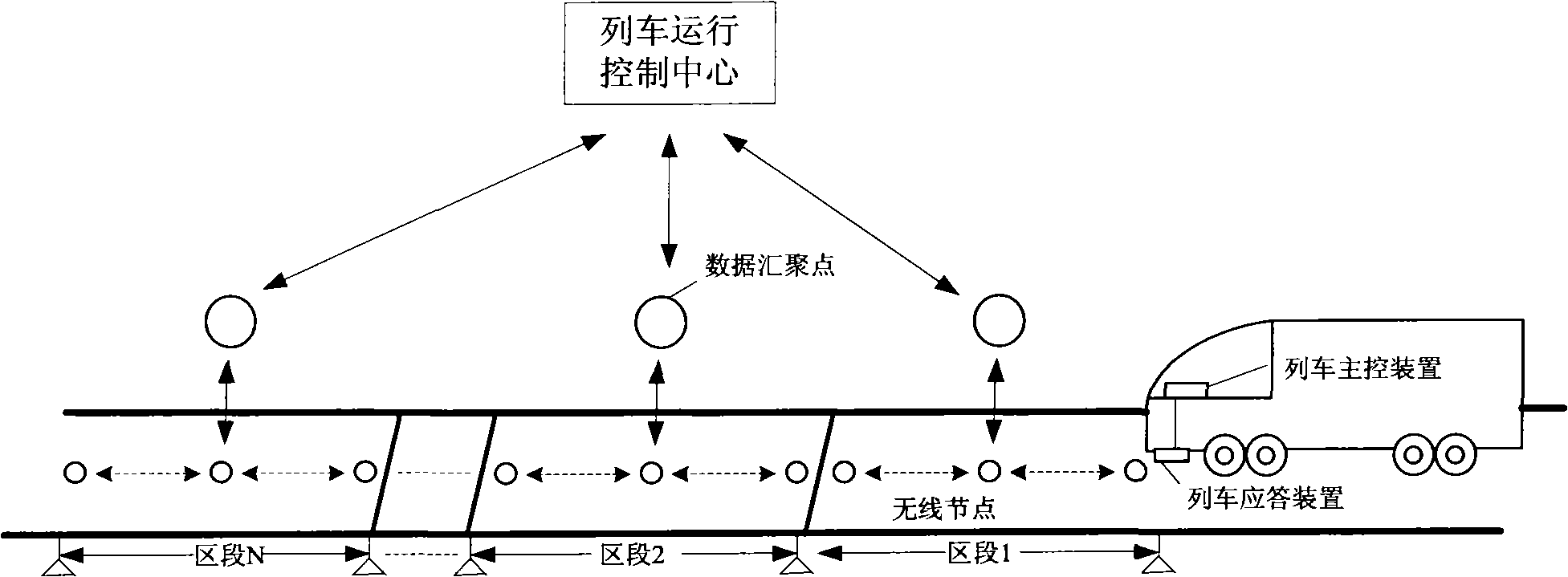
[0050] In order to realize the object of the present invention, adopt following scheme, as figure 1 As shown, the main control device is first installed on the train, and the response device for sending the train arrival signal is installed at the bottom of the train head.

[0051] Divide the railway line into multiple sections, and lay multiple wireless nodes and a data aggregation point evenly in each section. The wireless nodes in each section form a wireless network in a self-organizing manner and communicate with the wireless nodes in the section. The data convergence point communicates. In addition, the data convergence point also communicates with the train operation control center; the wireless node stores the railway location information where it is located;

...


PUM


Abstract

The invention discloses a train temporary speed-limiting method based on a self-organizing network. The method comprises the following steps of: dividing a train line into a plurality of sections, paving a plurality of wireless nodes and a data convergent point in each section, and assigning the corresponding node as the speed-limiting node by a train running control center through the data convergent point. When the train passes through the target section, a train responding device generates a train arriving signal, and all normal operation nodes in the target section can receive the signal. When the train passes through the position in which each node is located, the train responding device collects the speed-limiting information generated by the speed-limiting node and sends the information to a train master control device in order to control the traveling speed. Compared with the prior art, the method based on self-organizing network can realize that the speed-limiting command is quickly issued, the speed-limiting information is accurately configured, the manual patrol workload is reduced, the road station information is accurately reported to the control center in time, and the traveling safety of the train is enhanced.

Description

technical field [0001] The invention relates to the field of railway train operation safety, in particular to a temporary train speed limiting method based on an ad hoc network. Background technique [0002] In order to ensure the safety of train operation, speed limit operation is often required during train running. At present, my country's railway management department has two ways to limit the speed of trains: inherent speed limit and temporary speed limit. For the inherent speed limit of the road section, the speed limit can be realized by pre-setting the vehicle-mounted operation monitoring device (LKJ device), which reduces the influence of human factors and improves driving safety; when an emergency or temporary construction along the railway line requires temporary When the speed is limited, the driving information of the on-board LKJ device cannot be updated in time, and the method of informing the driver of the speed limit by placing a temporary speed limit sign ...

Claims


Application Information

Patent Timeline
IPC IPC(8): B61L1/00B61L13/04B61L23/00H04W84/18
Inventor 谢胜利吴俊强刘震宇
Owner SOUTH CHINA UNIV OF TECH
Learn More