
Metal bar material conveying device and application method thereof

A technology of conveying device and metal bar, which is applied in the direction of conveyor control device, conveyor objects, transportation and packaging, etc., can solve the problem of high labor intensity of operators, and achieve the effect of eliminating labor links.

Active Publication Date: 2010-07-28
SHENYANG NEU-SANKEN IND FURNACE MFG CO LTD
View PDF0 Cites 11 Cited by
  • Summary
  • Abstract
  • Description
  • Claims
  • Application Information

AI Technical Summary

Problems solved by technology

[0002] In the automatic production line for forging aluminum alloy wheels, the rod-shaped blanks need to be continuously fed into the heating furnace for heating. The ordinary feeding mechanism can only rely on manual handling to arrange the blanks into a single layer or directly rely on manual feeding, which is labor-intensive for operators. great

Method used


Image

  • Metal bar material conveying device and application method thereof
  • Metal bar material conveying device and application method thereof
  • Metal bar material conveying device and application method thereof

Examples


Embodiment Construction

[0025] The detailed structure of a metal bar conveying device and application method of the present invention will be described in conjunction with embodiments.

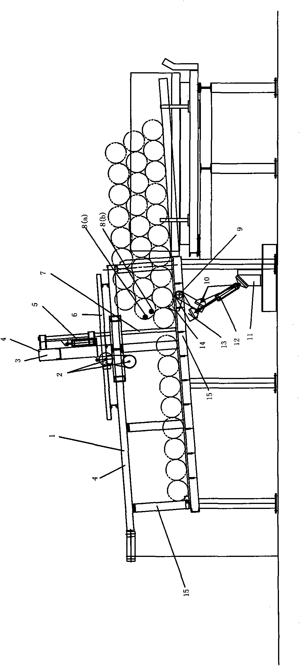
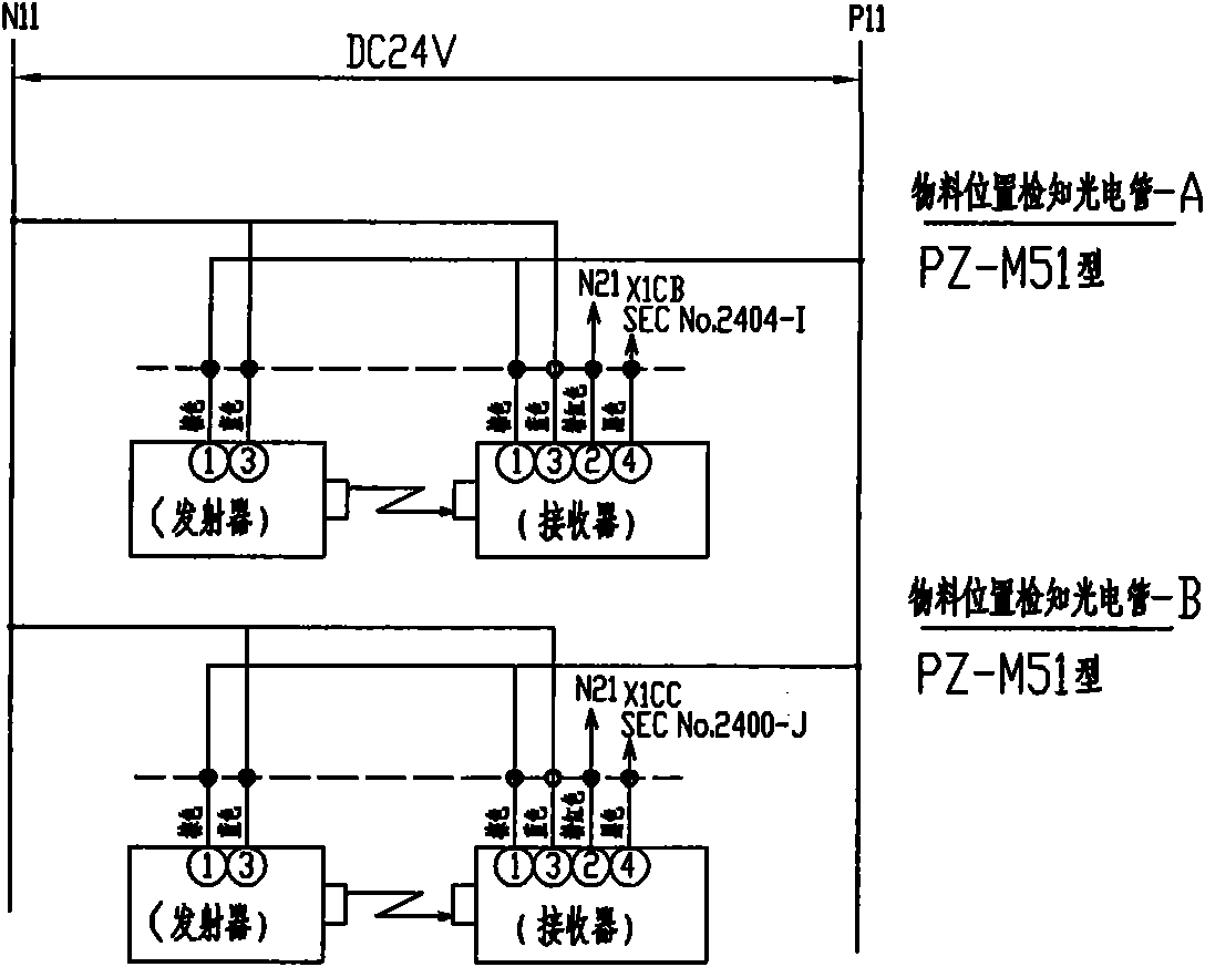
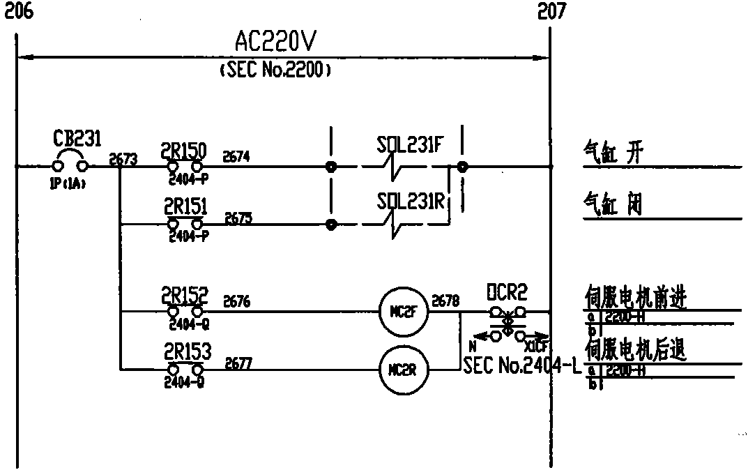
[0026] The present invention as figure 1 As shown, its structure includes an electric control part, a fixed guide rail 1, a moving mechanism and a blocking mechanism, wherein the electric control part includes a PLC control device, a photoelectric switch A8 (a), a photoelectric switch B8 (b), a group of cylinder solenoid valves, A servo motor 2, an electric push cylinder 5 and two groups of limit switches 4, the photoelectric switch A8 (a) and the photoelectric switch B8 (b) all include a photoelectric transmitter and a photoelectric receiver; the moving mechanism includes a moving guide rail 6, When moving the material plate 7 and moving the support beam 3, the blocking mechanism includes blocking the swing arm 14, the cylinder 12, the active swing arm 13, the base 11 and the swing arm shaft 9; the connection relati...


PUM


Abstract

The invention relates to a metal bar material conveying device and an application method thereof, belonging to the technical field of alloy production raw material conveying machinery. The device comprises an electric control part, a fixed guide rail, a moving mechanism and a blocking mechanism; and the application method of the device enables the device to achieve the function of controlling the speed of materials in the first row and discontinuously actuating materials in the second row and the whole material pile thereafter. By organically combining the supplied material conveying and the automatic feeding, the device omits the intermediate manual link, extends the automation procedure, can simultaneously be extended to other industries in which the automatic bar material conveying is necessary, and is especially applicable to the bar material of which the ratio of length to diameter is less than 2.

Description

technical field [0001] The invention belongs to the technical field of conveying machinery for alloy production raw materials, in particular to an automatic conveying device for rod-shaped materials, which can automatically and orderly convey stacked rods. Background technique [0002] In the automatic production line for forging aluminum alloy wheels, the rod-shaped blanks need to be continuously fed into the heating furnace for heating. The ordinary feeding mechanism can only rely on manual handling to arrange the blanks into a single layer or directly rely on manual feeding, which is labor-intensive for operators. great. Contents of the invention [0003] Aiming at the deficiencies in the prior art, the present invention provides a metal bar conveying device and its application method, which is used to release the stacked bars in alloy production in an orderly manner, and through the multi-layer bars stacked on the transfer rack The materials are automatically and orde...

Claims


Application Information

Patent Timeline
Patent Type & Authority Applications(China)
IPC IPC(8): B65G43/08B65G47/88F27D3/00B21J1/06
Inventor 李正
Owner SHENYANG NEU-SANKEN IND FURNACE MFG CO LTD
Learn More