Stabilizer bar conveying and clamping device

A transmission device and stabilizing bar technology, which is applied in the field of stabilizing bar transmission and clamping devices, can solve problems such as prone to safety accidents and low efficiency

Pending Publication Date: 2019-02-22
贵州长江汽车有限公司
View PDF0 Cites 0 Cited by
  • Summary
  • Abstract
  • Description
  • Claims
  • Application Information

AI Technical Summary

Problems solved by technology

[0003] In the existing automobile stabilizer bar processing technology, there are problems of low efficiency and easy safety

Method used


Image

  • Stabilizer bar conveying and clamping device
  • Stabilizer bar conveying and clamping device
  • Stabilizer bar conveying and clamping device

Examples


Embodiment 1

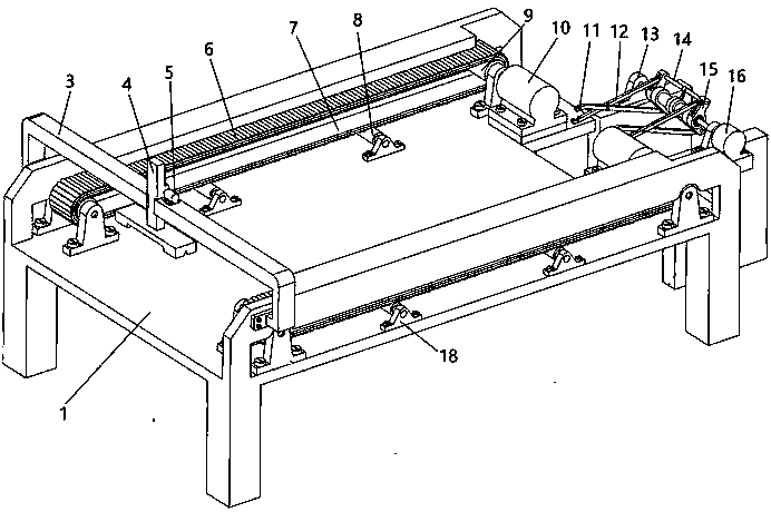
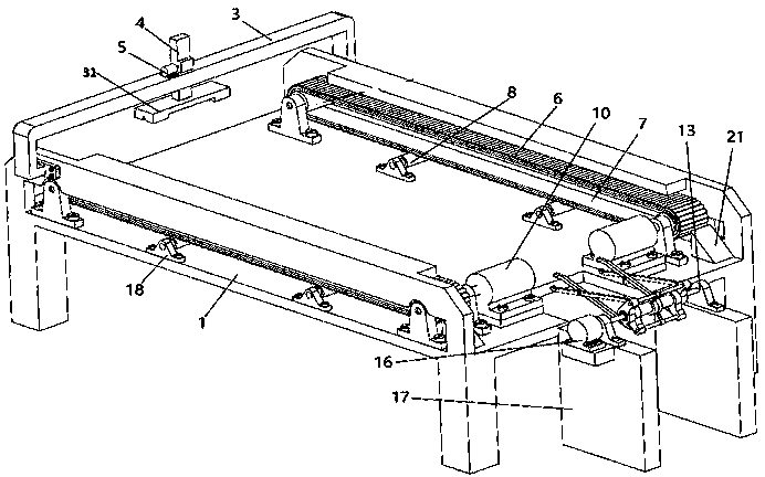
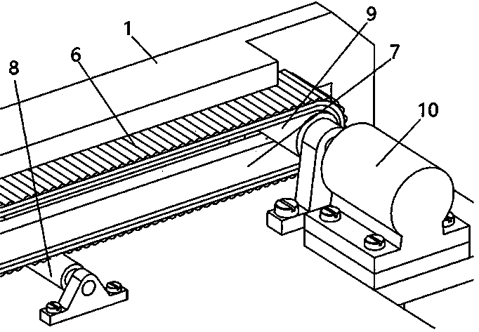
[0020] Example 1. As figure 1 Shown, a kind of stabilizing rod conveying clamping device, it comprises conveying base 1, is provided with vertical baffle plate on both sides of conveying base 1, is provided with conveying device on conveying base 1, described conveying device comprises On both sides of the transmission base 1, there are supporting bases II18 evenly arranged on both sides. On the supporting base II18, a drag roller 8 is installed. The motor drum 9 is provided with a conveyor belt heat insulation layer 6 on the outside of the conveyor belt 7, and the outside of the conveyor belt heat insulation layer 6 is provided with protrusions arranged seamlessly; a straightening device is respectively provided at the head end and the tail end of the transmission device and clamping device; the straightening device includes a crossbar 3 provided on the transmission base 1, a groove I is provided in the middle of the crossbar 3, and a straightening column 4 and a straightenin...


PUM


Abstract

The invention discloses a stabilizer bar conveying and clamping device. The stabilizer bar conveying and clamping device comprises a conveying base (1), and a conveying device is arranged on the conveying base (1). The stabilizer bar conveying and clamping device is characterized in that an aligning device and a clamping device are arranged at the head end and the tail end of the conveying devicerespectively. According to the stabilizer bar conveying and clamping device, manual operation can be reduced, the machining efficiency is improved, and meanwhile, the accident that worker is scalded by a high-temperature stabilizer bar during manual operation is also avoided.

Description

technical field [0001] The invention relates to a stabilizer bar transmission and clamping device, which belongs to the field of locomotive production tools. Background technique [0002] The car stabilizer bar, also known as the anti-roll bar, is an auxiliary elastic component in the car suspension system. Its function is to prevent excessive lateral roll of the body when turning. The purpose is to prevent the car from overturning laterally and improve the stability and ride comfort when cornering. [0003] In the existing automobile stabilizer bar processing technology, there are problems of low efficiency and easy safety accidents caused by manual operation during the process of installing it on the forming bending machine after heat treatment. The specific manifestation is: when the stabilizer bar is bent after heat treatment, the accident of being scalded by the high temperature stabilizer bar during manual operation. [0004] That is: there is a need for a stabilizi...

Claims


Application Information

Patent Timeline
IPC IPC(8): B21D43/00B21D43/10
CPCB21D43/003B21D43/006B21D43/10
Inventor 杨楠
Owner 贵州长江汽车有限公司
Why Eureka
Try Eureka