Full-automatic non-negative pressure water supply equipment and water supply method
A water supply equipment, no negative pressure technology, applied in the water supply main pipeline, water supply pipeline system, water supply device and other directions, can solve the problem of unreasonable user responsibility, and achieve the effect of stable pressure
- Summary
- Abstract
- Description
- Claims
- Application Information
AI Technical Summary
Problems solved by technology
Method used
Image
Examples
Embodiment 1
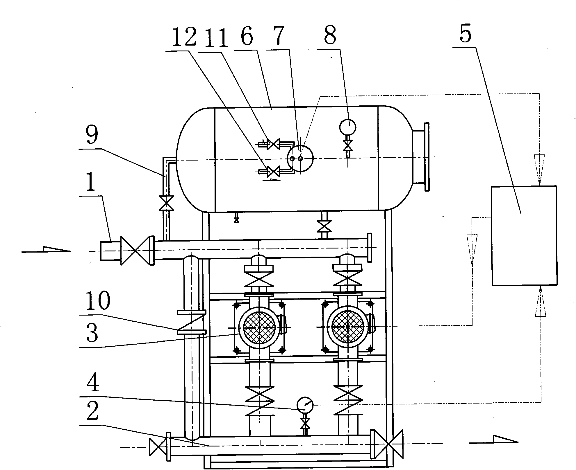
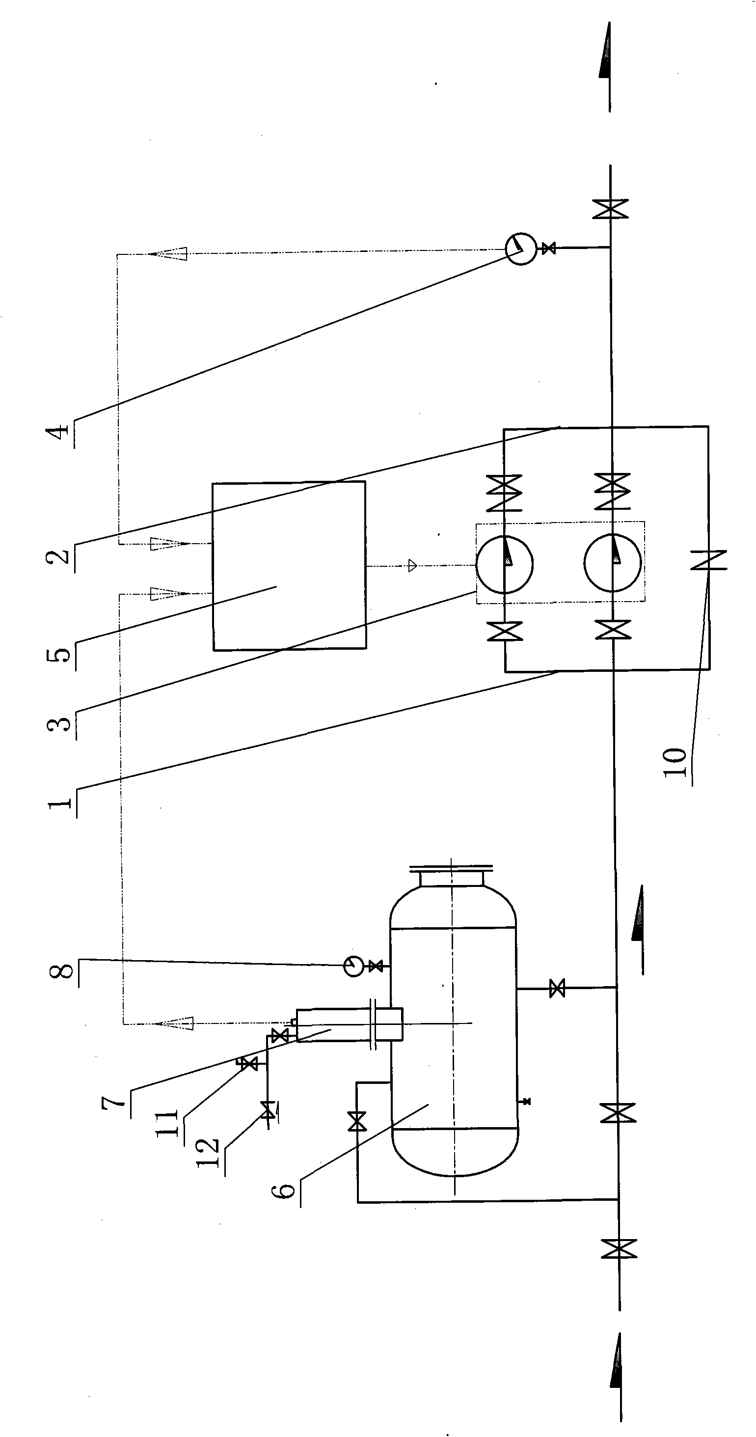
[0018] Fully automatic non-negative pressure water supply equipment, its composition includes: the source pipeline 1 connected to the water source, the two pipelines between the source pipeline and the water supply pipeline 2 connected to the user are respectively connected to the water pump 3, the water supply pipeline The pipeline is connected to the outlet pressure detector 4, the outlet pressure detector is connected to the control device 5, the control device is connected to the inlet pressure detector 7 on the buffer tank 6, the pressure gauge 8 is connected to the buffer tank, and the The control device described above drives the water pump, and the buffer tank is connected to the source pipeline through a pipeline 9 with a valve. The lower end of the fully automatic non-negative pressure water supply equipment has a base.
Embodiment 2
[0020] The above-mentioned fully automatic non-negative pressure water supply equipment, the control device includes a programmable controller 14, the programmable controller is respectively connected to the text display 15 and the frequency converter 16, and the frequency converter is connected to the water pump by the circuit connection relationship Motor 17, the water pump motor drives the water pump 3.
Embodiment 3
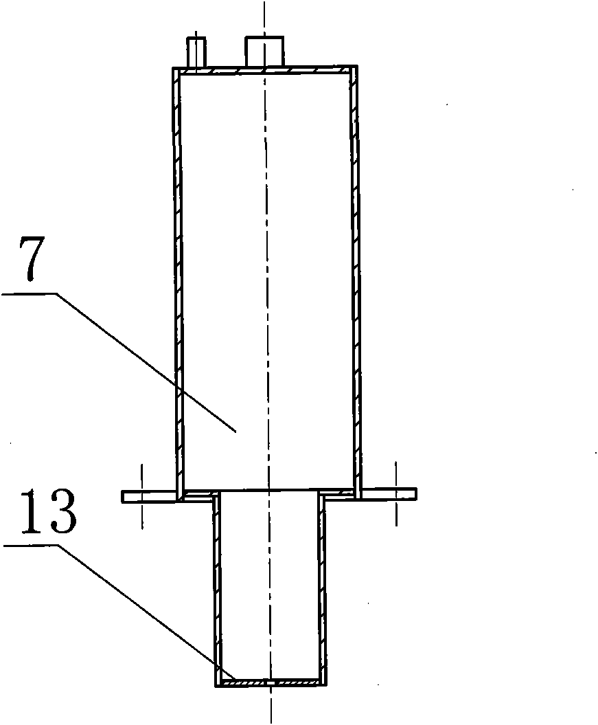
[0022] In the above-mentioned fully automatic non-negative pressure water supply equipment, there is a check valve 10 on the pipeline connected between the source pipeline and the water supply pipeline; the inlet pressure detector is connected to the automatic exhaust valve 11 and the suction valve 12 , the inlet pressure detector has a damping hole 13 at the bottom.
[0023] attached figure 2 The inlet pressure detector shown is a cylindrical container with small damping holes. The function of the damping holes is to eliminate the instantaneous fluctuation of the liquid level or pressure of the pipe network.
PUM
 Abstract
Description
Claims
Application Information
 - R&D
- Intellectual Property
- Life Sciences
- Materials
- Tech Scout
- Unparalleled Data Quality
- Higher Quality Content
- 60% Fewer Hallucinations
Browse by: Latest US Patents, China's latest patents, Technical Efficacy Thesaurus, Application Domain, Technology Topic, Popular Technical Reports.
© 2025 PatSnap. All rights reserved.Legal|Privacy policy|Modern Slavery Act Transparency Statement|Sitemap|About US| Contact US: help@patsnap.com


