
Valve timing control apparatus

A technology of valve timing control and fluid control valves, which is applied in the direction of valve devices, engine components, machines/engines, etc., and can solve the problems of deteriorating the installability of valve timing control devices, lengthening the longitudinal length of valve timing control devices, etc.

Inactive Publication Date: 2010-07-28
AISIN SEIKI KK
View PDF1 Cites 9 Cited by
  • Summary
  • Abstract
  • Description
  • Claims
  • Application Information

AI Technical Summary

Problems solved by technology

Therefore, when maintaining a sufficient spool length, the longitudinal length of the valve timing control device is lengthened, and the mountability of the valve timing control device on the engine may be deteriorated

Method used


Image

  • Valve timing control apparatus
  • Valve timing control apparatus
  • Valve timing control apparatus

Examples


Embodiment Construction

[0030] [the whole frame]

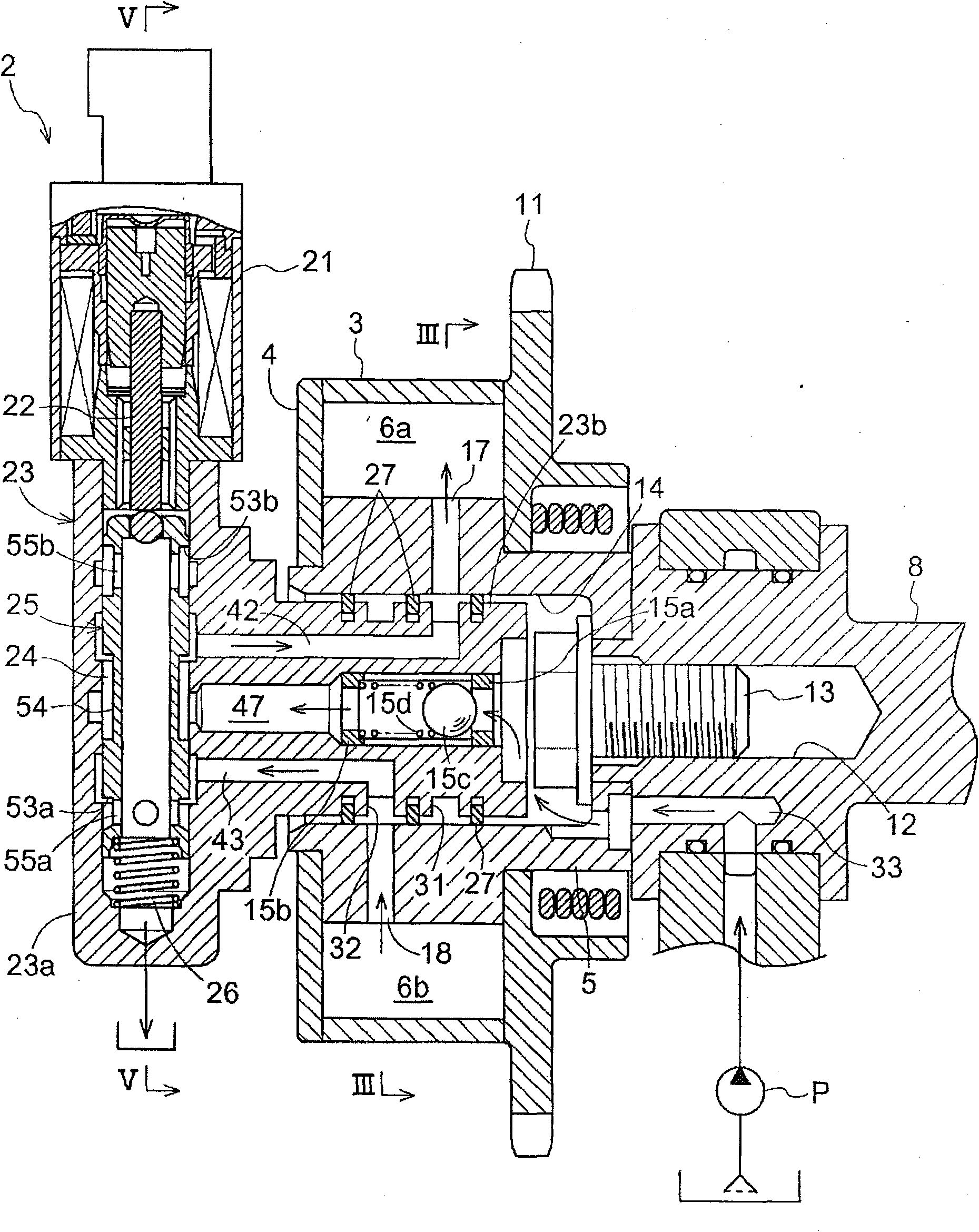
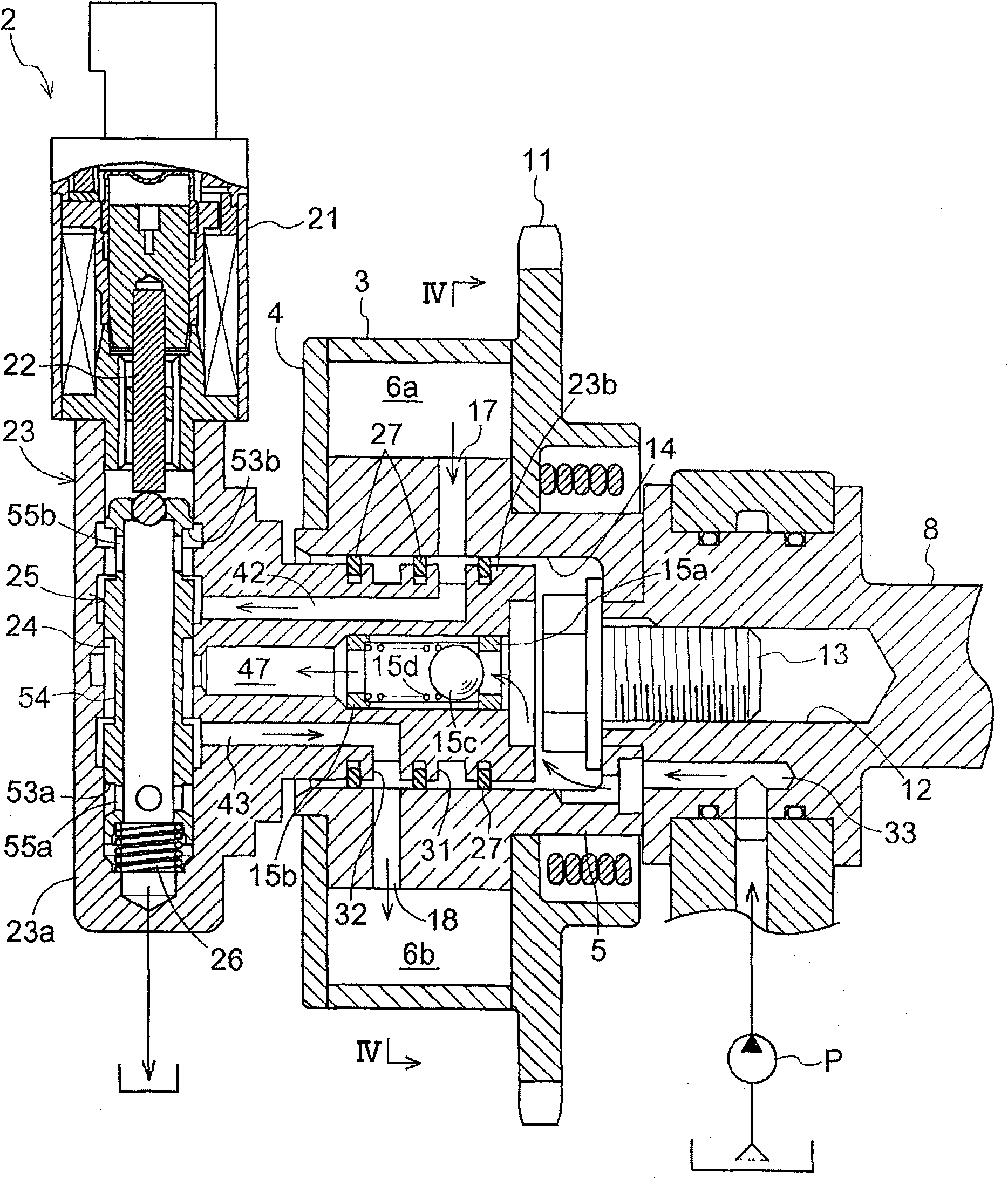
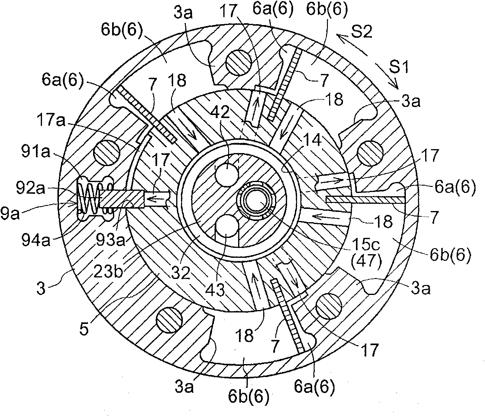
[0031] Such as figure 1As shown, a valve timing control device 1 according to one embodiment includes an outer rotor 3 (driving side rotating member), a front plate 4, and an inner rotor 5 (driven side rotating member). The outer rotor 3 and the front plate 4 rotate synchronously with the crankshaft of the engine. The inner rotor 5 is coaxially arranged with the outer rotor 3 . The outer rotor 3 rotates synchronously with the camshaft 8 for opening and closing the engine valves. The inner rotor 5 is integrally arranged on the end of the camshaft 8, the camshaft 8 constitutes the rotating shaft of the cam, and the cam is used to control the opening and closing of the intake valve and the exhaust valve of the engine. The recess 14 is formed on the radial inner side of the inner rotor 5 (the axis side of the camshaft 8 ) so as to open toward the opposite side of the camshaft 8 (to open toward the front plate 4 ). Furthermore, a fixing hole 12 is for...


PUM


Abstract

A valve timing control apparatus (1) includes a driving side rotational member (3), a driven side rotational member (5), an advanced angle chamber (6a) and a retarded angle chamber (6b), and a fluid control valve portion (2) arranged orthogonally relative to the camshaft (8) at an opposite side of the camshaft (8) so as to dispose the driving side rotational member (3) and the driven side rotational member (5) between the fluid control valve portion (2) and the camshaft (8), the fluid control valve portion (2) including a first linearly moving member (25) linearly moving in an orthogonal direction relative to the camshaft (8), thereby controlling supplying and discharging of a fluid relative to the advanced angle chamber (6a) and the retarded angle chamber (6b).

Description

technical field [0001] The present disclosure relates to a valve timing control device for controlling a relative rotational phase of a driven side rotating member with respect to a driving side rotating member which rotates synchronously with a crankshaft of an internal combustion engine. Background technique [0002] A well-known valve timing control device disclosed in JP2004-340142A includes: a hydraulic chamber formed at one of the driving side rotating member and the driven side rotating member; and a partition formed at the driving side rotating member and the driven side rotating member. The other part of the rotating part of the moving side is used to divide the hydraulic chamber into an advanced angle chamber and a retarded angle chamber. The fluid supplied or discharged with respect to the advanced angle chamber or the retarded angle chamber is controlled, thereby controlling the relative rotational phase of the driven side rotational member with respect to the dr...

Claims


Application Information

Patent Timeline
IPC IPC(8): F01L1/34
CPCF01L2001/34476F01L1/3442F01L2001/3443F01L2001/34483F01L2001/34433F01L1/34406F01L2001/34426
Inventor 铃木重光稻摩直人朝日丈雄
Owner AISIN SEIKI KK
Learn More