Supercharge Your Innovation With Domain-Expert AI Agents!

Camera fixing device

A fixing device and camera technology, which is applied in the field of cameras, can solve problems such as inability to effectively guarantee coaxiality, and achieve better photography effects, ensure stability, and fix and reliable effects

Inactive Publication Date: 2011-11-23
SAE ELECTRONICS
View PDF0 Cites 0 Cited by
  • Summary
  • Abstract
  • Description
  • Claims
  • Application Information

AI Technical Summary

Problems solved by technology

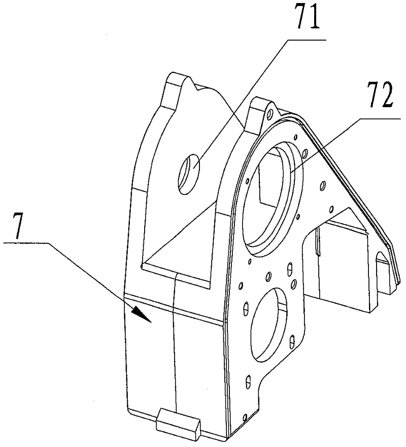
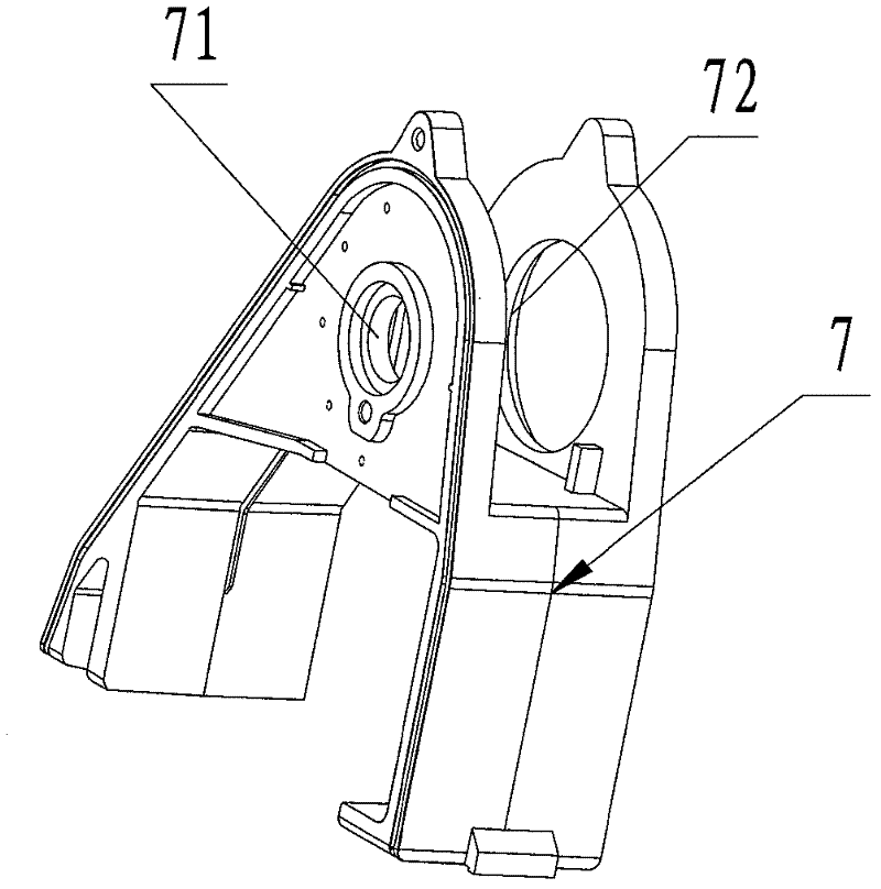
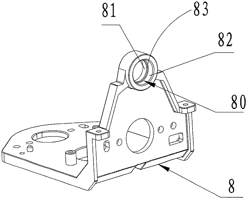
When the mold is die-casting, the mold opening direction is parallel to the direction of the fixing hole 80, and there is still a draft angle inherent in mold making, which requires machining in the later stage, so that the coaxiality cannot be effectively guaranteed

Method used


Image

  • Camera fixing device
  • Camera fixing device
  • Camera fixing device

Examples


Embodiment Construction

[0025] refer to Figure 4 , the camera fixing device of the present invention is used to install the camera assembly, including: a fixing frame 1 and two bearing glands 2 installed on the fixing frame 1 .

[0026] refer to Figure 4 , the fixed frame 1 includes: a bottom plate 11, a first fixed plate 12 and a second fixed plate 13 respectively arranged on both sides of the bottom plate 11, the bottom plate 11 is parallel to the XY plane, the first fixed plate 12 and the second fixed plate The fixed plates 13 are all perpendicular to the bottom plate 11; the upper ends of the first fixed plate 12 and the second fixed plate 13 are provided with a fixed portion 14, and the fixed portion 14 is roughly semicircular, and the middle part is provided with a fixed hole 10 And the block 15 that is positioned at fixed hole 10 both sides, is used for installing the bearing 32 on the power transmission shaft 31 (referring to Image 6 ); fixed blocks 16 are provided on both sides of the f...


PUM


Abstract

The invention relates to a camera fixing device, which comprises a mounting bracket (1). The mounting bracket (1) comprises a base plate (11), a first fixing plate (12) and a second fixing plate (13), wherein the base plate (11) is used for arranging a drive motor; the first fixing plate (12) and the second fixing plate (13) are arranged on the two sides of the base plate (11) and used for arranging a drive shaft (31); the base plate (11) is parallel to an XY plane; the first fixing plate (12) and the second fixing plate (13) are vertical to the base plate (11) and correspondingly provided with mounting holes (10) for arranging bearings (32) of the drive shaft (31); and the line of centers of the two mounting holes (10) is parallel to an X shaft so as to ensure the coaxiality of the two mounting holes. The camera fixing device of the invention makes the two mounting holes have good coaxiality, and because the two mounting holes are used to arrange the two bearings on the drive shaft, the running stability of the drive shaft is ensured.

Description

technical field [0001] The invention relates to the field of cameras, more specifically, to a camera fixing device capable of ensuring coaxiality. Background technique [0002] At present, the photographic cameras used in the electronics industry and the security photography monitoring industry usually include a drive motor, a camera component, and a lighting component. The drive motor drives the camera component and the lighting component through a transmission device. The transmission device includes a transmission shaft, a transmission pulley, etc. The transmission pulley is installed on the transmission shaft, and the two ends of the transmission shaft are respectively connected to the camera assembly and the lighting assembly. The transmission pulley is connected to the driving motor through a transmission belt, and the power of the driving motor is transmitted to the transmission pulley, and the transmission pulley transmits the power to the transmission On the shaft, ...

Claims


Application Information

Patent Timeline
Patent Type & Authority Patents(China)
IPC IPC(8): G03B17/56F16M11/04
Inventor 伍志坚赵红钦
Owner SAE ELECTRONICS
Features
  • R&D
  • Intellectual Property
  • Life Sciences
  • Materials
  • Tech Scout
  • Unparalleled Data Quality
  • Higher Quality Content
  • 60% Fewer Hallucinations
Learn More