Light-emitting diode (LED) car lamp device

A technology for light-emitting diodes and vehicle lights, which is applied to lighting devices, fixed lighting devices, and loss prevention measures for lighting devices, etc., can solve problems such as influence, and achieve the effect of improving heat dissipation efficiency.

Inactive Publication Date: 2010-07-28
BRIGHT LED ELECTRONICS CORP
View PDF0 Cites 6 Cited by
  • Summary
  • Abstract
  • Description
  • Claims
  • Application Information

AI Technical Summary

Problems solved by technology

[0006] The purpose of the present invention is to overcome the problem that the high temperature of the existing car body easily affects the car light device. The purpose of the present invention is to provide a light-emitting diode car light device with a new structure. The technical problem to be solved is to make it It can reduce or even prevent the high temperature of the car body from entering the lamp device and affecting its performance

Method used


Image

  • Light-emitting diode (LED) car lamp device
  • Light-emitting diode (LED) car lamp device
  • Light-emitting diode (LED) car lamp device

Examples


Embodiment Construction

[0027] In order to further explain the technical means and effects of the present invention to achieve the intended purpose of the invention, the specific implementation, structure, characteristics and features of the light-emitting diode lamp device proposed according to the present invention will be described below in conjunction with the accompanying drawings and preferred embodiments. Efficacy, detailed as follows.

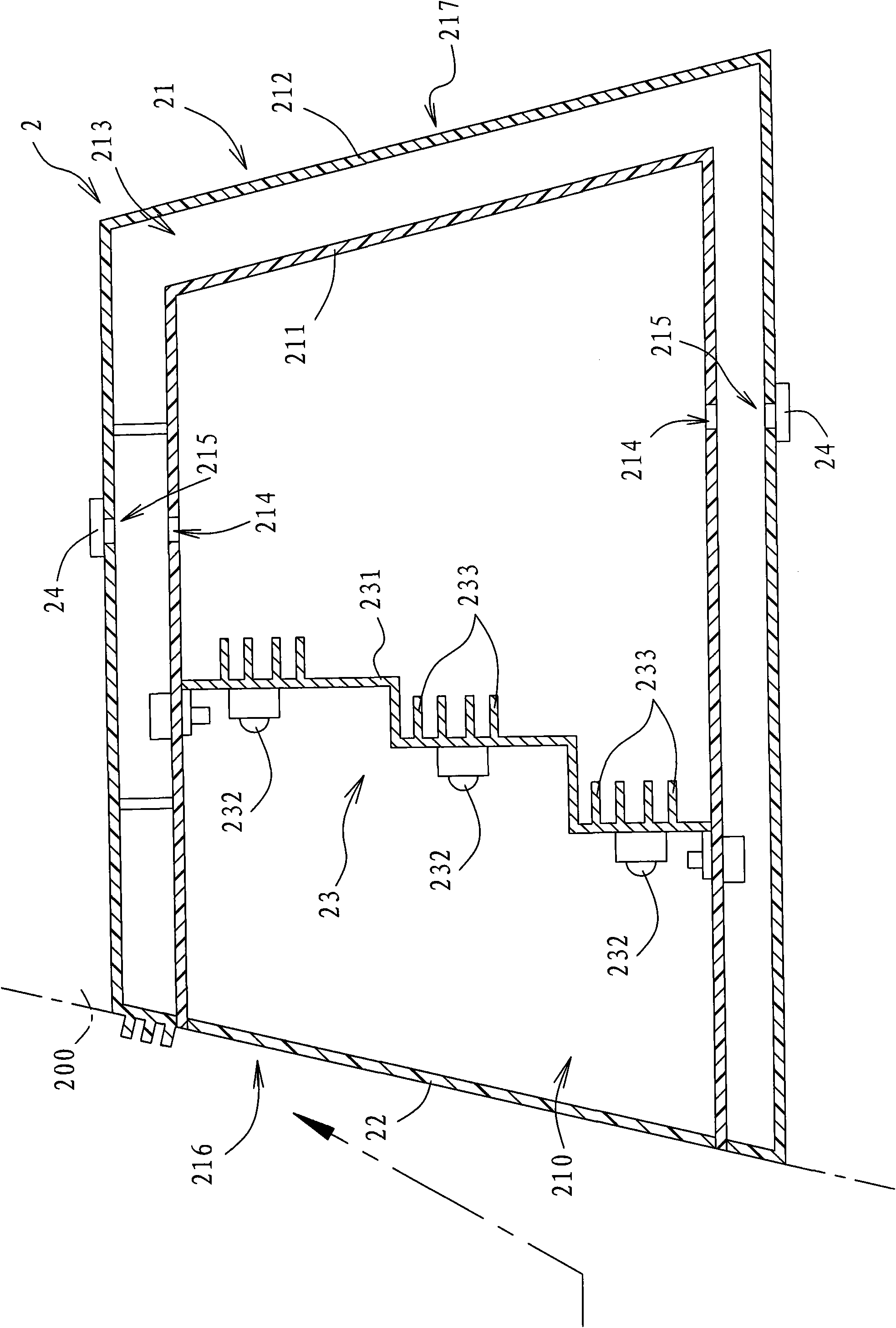
[0028] refer to figure 2 , the first preferred embodiment of the LED vehicle lamp device 2 of the present invention is disposed in a vehicle body 200 , and the LED vehicle lamp device 2 includes a casing 21 , a light-transmitting lampshade 22 and a light emitting module 23 .

[0029] The housing 21 defines an inner space 210 and includes an inner layer 211 and an outer layer 212 combined with the inner layer 211 and surrounding the inner layer 211, and the thermal conductivity of the outer layer 212 is lower than that of the inner layer 211 , in this embodim...


PUM

PropertyMeasurementUnit
Thermal conductivityaaaaaaaaaa

Abstract

The invention relates to a light-emitting diode (LED) car lamp device which comprises a shell, a light-transmitting lampshade and an LED module. The shell and the light-transmitting lampshade are combined to define an internal space, the LED module is arranged in the internal space, and the shell comprises an inner layer and an outer layer which is combined with and encircled around the inner layer, wherein the outer layer has a heat conductivity coefficient lower than that of the inner layer for preventing temperature outside the shell from being conducted into the shell, and thereby increasing the temperature in the shell or influencing the operation of the LED module.

Description

technical field [0001] The invention relates to a vehicle light device, in particular to a light emitting diode vehicle light device. Background technique [0002] refer to figure 1 , is a conventional light-emitting diode lamp device 1 of Japan Koito Company, which includes a housing 11, a light-transmitting lampshade 12 combined with the housing 11, a base 13 arranged in the housing 11, and a plurality of bases arranged on the base The light emitting diode 14 of the base 13 , and the base 13 is formed with a plurality of cooling fins 131 . [0003] The position where the light-transmitting lampshade 12 is located is in front of the entire vehicle light device 1. When the vehicle light device 1 is installed on the vehicle body 100, the heat energy generated inside the vehicle light device 1 (for example, from the light emitting diode 14) is generated by the The cold air blown to the light-transmitting lampshade 12 (shown by the imaginary line arrow in the figure) exchange...

Claims


Application Information

Patent Timeline
IPC IPC(8): F21S8/10F21V15/02F21V15/06F21V29/00F21Y101/02F21W101/02F21V29/60F21V29/74F21W107/10
Inventor 李承士谢馨仪殷寿志
Owner BRIGHT LED ELECTRONICS CORP
Why Eureka
Try Eureka