Zoom infrared imaging pan-tilt

An infrared imaging and gimbal technology, applied in the field of drones, can solve the problems of gimbal waterproofness, insufficient stability, cumbersome assembly process, etc., and achieve the effect of simplifying the assembly and maintenance process, ensuring clarity, and convenient disassembly and assembly

Inactive Publication Date: 2017-02-22
TIANJIN ZHONGXIANGTENGHANG SCI & TECH CO LTD
View PDF0 Cites 8 Cited by
  • Summary
  • Abstract
  • Description
  • Claims
  • Application Information

AI Technical Summary

Problems solved by technology

[0003] In view of this, the present invention aims to propose a variable-focus infrared imaging pan / tilt to solve the problems in the prior art that the pan / tilt is not waterproof, stable enough, and the assembly process is cumbersome.

Method used


Image

  • Zoom infrared imaging pan-tilt
  • Zoom infrared imaging pan-tilt
  • Zoom infrared imaging pan-tilt

Examples


Embodiment Construction

[0023] It should be noted that, in the case of no conflict, the embodiments of the present invention and the features in the embodiments can be combined with each other.

[0024] In describing the present invention, it should be understood that the terms "center", "longitudinal", "transverse", "upper", "lower", "front", "rear", "left", "right", " The orientations or positional relationships indicated by "vertical", "horizontal", "top", "bottom", "inner" and "outer" are based on the orientations or positional relationships shown in the drawings, and are only for the convenience of describing the present invention and Simplified descriptions, rather than indicating or implying that the device or element referred to must have a particular orientation, be constructed and operate in a particular orientation, and thus should not be construed as limiting the invention. In addition, the terms "first", "second", etc. are used for descriptive purposes only, and should not be understood ...


PUM


Abstract

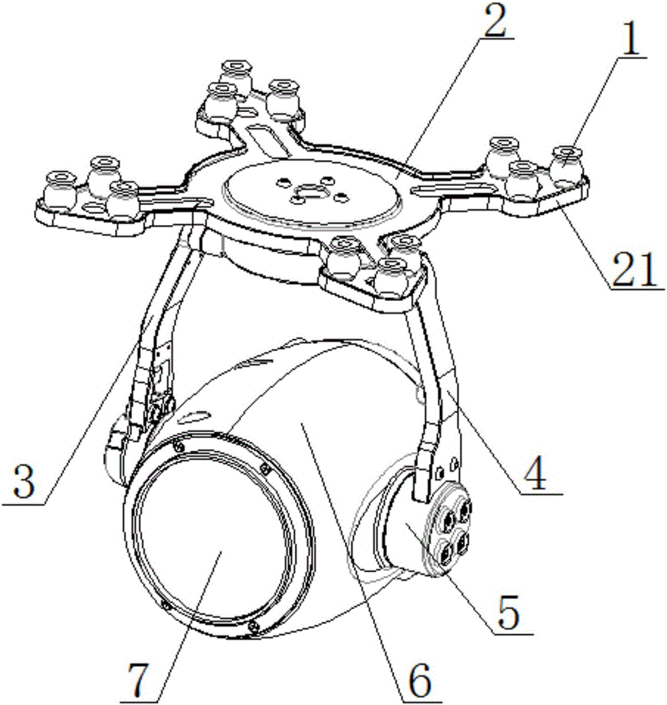
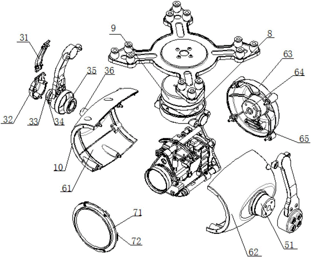
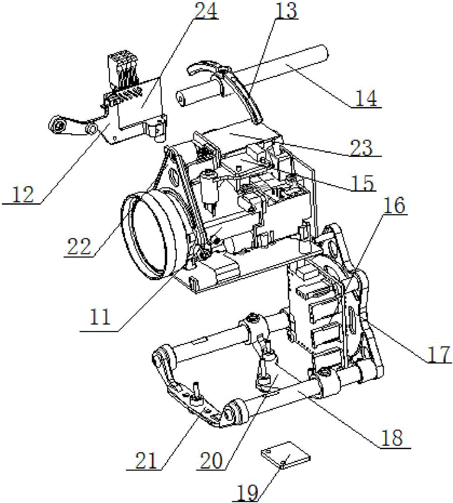
The invention provides a zoom infrared imaging pan-tilt. The pan-tilt comprises a universal fixing frame, a hanging bracket and a shell, wherein the lower end of the universal fixing frame is rotationally connected with the hanging bracket through a translational motor; the hanging bracket comprises a vertical downward left universal hanging arm and a vertical downward right universal hanging arm, and the two universal hanging arms are symmetrically arranged and rotationally connected with the middle of the side wall of the shell at the same time; a pitching motor is installed between the left universal hanging arm and the shell or between the right universal hanging arm and the shell; the shell is arranged between the left universal hanging arm and the right universal hanging arm, a UV lens is fixedly connected with the front end of the shell, and the inner side wall of the shell is rotationally connected with the zoom camera through a rolling motor; the universal fixing frame, the hanging bracket and the shell are all made of nylon. The zoom infrared imaging pan-tilt is simple in structure, convenient to disassemble and assemble and high in water resistance, and photographed images are high in definition. The universal fixing frame, the hanging bracket and the shell made of nylon reduce the overall weight of the pan-tilt, abrasion resistance is improved, and cooling is facilitated. A modular structure is used, and the assembly and maintenance processes are simplified.

Description

technical field [0001] The invention belongs to the field of unmanned aerial vehicles, and in particular relates to an imaging platform for unmanned aerial vehicles. Background technique [0002] Most of the existing unmanned aerial vehicles will be equipped with camera equipment to complete the task of high-altitude aerial photography. With the rapid development of UAVs today, the supporting gimbals are naturally attracting attention. The existing cloud platform has poor waterproof effect in humid environment because it exposes the camera instrument. At the same time, there is a problem of complicated disassembly and assembly during assembly and maintenance of the existing pan / tilt. In addition, since the camera equipment installed on the existing pan / tilt cannot realize automatic zooming, the pictures taken during high-altitude surveys are not clear. Contents of the invention [0003] In view of this, the present invention aims to propose a variable-focus infrared ima...

Claims


Application Information

Patent Timeline
Patent Type & Authority Applications(China)
IPC IPC(8): F16M11/06F16M11/18F16M13/02B64D47/08G03B17/56G03B13/36
CPCG03B13/36G03B17/561F16M11/043F16M11/06F16M11/18F16M13/02B64D47/08F16M2200/06
Inventor 王宇
Owner TIANJIN ZHONGXIANGTENGHANG SCI & TECH CO LTD
Why Eureka
Try Eureka