Supercharge Your Innovation With Domain-Expert AI Agents!

Generating device

A technology for generating devices and driving devices, which is applied in the direction of generators/motors, electrical components, etc., which can solve problems such as high safety concerns, radiation disasters, and high raw material costs, and achieve the effects of reducing energy loss, improving efficiency, and stabilizing electric energy

Inactive Publication Date: 2012-01-11
JUN DONG POWER
View PDF0 Cites 0 Cited by
  • Summary
  • Abstract
  • Description
  • Claims
  • Application Information

AI Technical Summary

Problems solved by technology

[0008] 2. The supply and cost of raw materials are high, the price is not stable for a long time, and the earth reserves are limited
[0009] 3. Serious damage to the natural environment and ecology during construction and operation
[0010] 4. After operation, the aftermath cost of equipment maintenance and pollution is difficult to calculate
[0011] 5. High security doubts, such as radiation disasters caused by nuclear power generation

Method used


Image

  • Generating device
  • Generating device
  • Generating device

Examples


Embodiment Construction

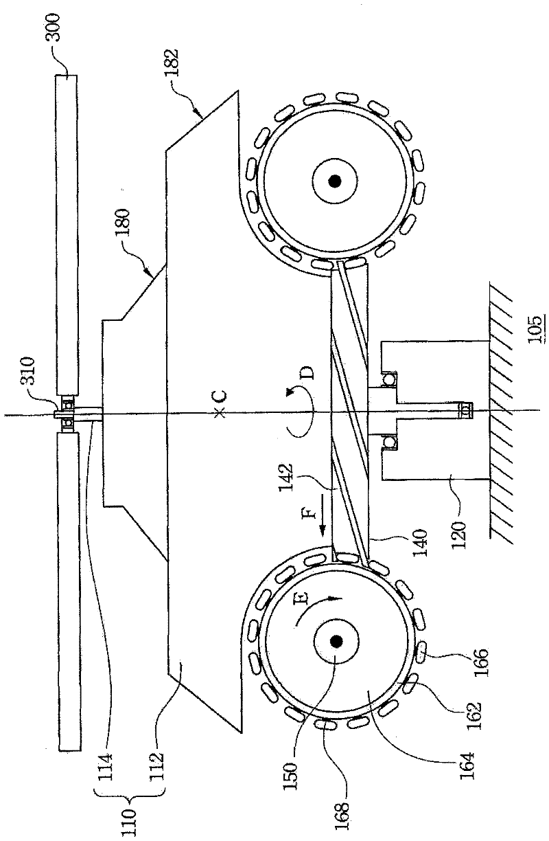
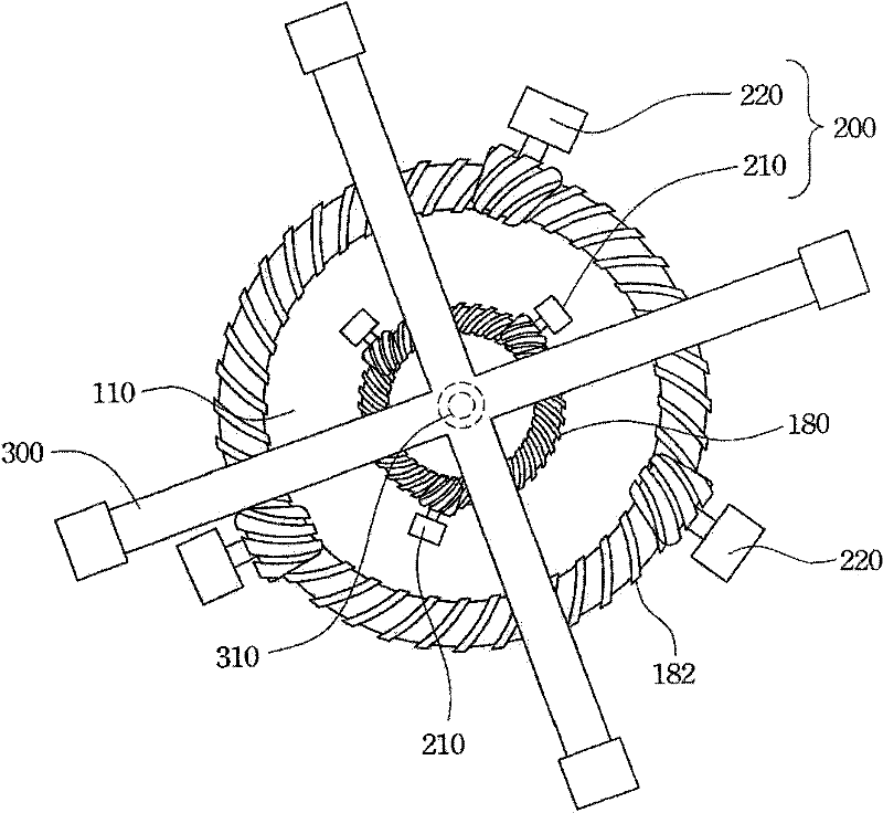
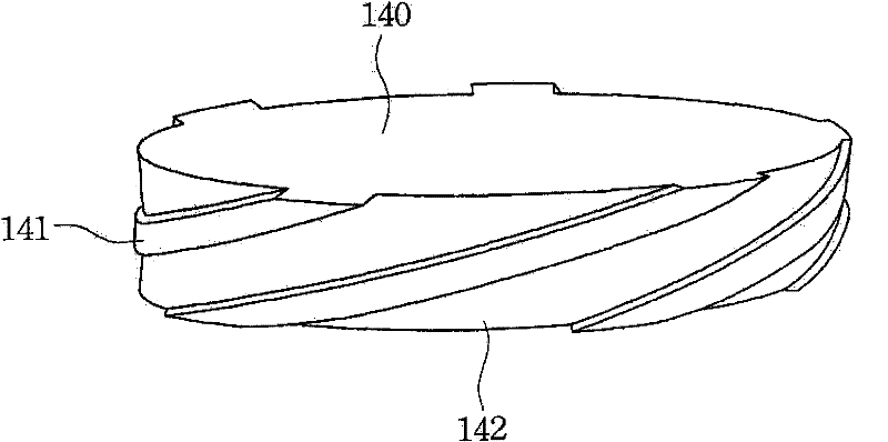
[0039] Such as figure 1 Shown, the sectional view of the power generation device of an embodiment of the present invention, figure 2 then figure 1 top view of the power plant. Such as figure 1 , 2 As shown, a power generating device mainly includes a gyro gravity body 110 , a bearing base 120 , a driving device 200 , a transmission disc 140 , a converting device 150 and a rotating wheel 164 .

[0040] Based on the above, the gyro gravity body 110 includes a body 112 and a rotating shaft 114 . The body 112 of the gyro gravity body is provided with a first gear ring 180 and a second gear ring 182, both of which are arranged on the body 112 with the rotating shaft 114 as the center, and the second gear ring 182 is arranged on the first gear ring 180 outside. Also, the second gear ring 182 has a larger diameter. The rotation axis 114 of the gyro gravity body 110 runs through the central axis of the main body 112 and is substantially perpendicular to the ground 105 .

[00...


PUM


Abstract

The invention discloses a generating device which comprises a gyro gravity body, a bearing base, a driving device, a transmission disc with at least one groove, a rotating wheel with at least one rolling piece and a conversion device. The gyro gravity body comprises a body and a rotating shaft which penetrates through a central shaft of the body and is approximately perpendicular to the ground, the bearing base is arranged on the ground and supports one end of the rotating shaft, the driving device is used for driving the gyro gravity body to rotate, the transmission disc with at least one groove is arranged on the gyro gravity body, at least one rolling piece is contained in the at least one groove on the transmission disc, and the conversion device is connected with the rotating wheel and used for converting the rotation of the rotating wheel into electric energy.

Description

technical field [0001] The invention relates to a gravity or inertial motor, in particular to a gravity or inertial motor using a flywheel. Background technique [0002] As far as power generation technology is concerned, the current global power generation technology can be roughly classified into rotating power generation and non-rotating power generation. In terms of rotating power generation, it mainly includes the following methods: [0003] 1. Hydroelectric power generation: the potential energy of water is converted into potential energy, which is driven by a turbine, converted into mechanical energy, and finally electrical energy. [0004] 2. Thermal power generation: including geothermal, oil, coal, natural gas, nuclear energy, solar energy, etc., which convert thermal energy into mechanical energy, and then turn the generator to generate electrical energy. [0005] 3. Wind power generation: use wind power to rotate generators to generate electricity. [0006] How...

Claims


Application Information

Patent Timeline
Patent Type & Authority Patents(China)
IPC IPC(8): H02N11/00
Inventor 蔡名竣
Owner JUN DONG POWER
Features
  • R&D
  • Intellectual Property
  • Life Sciences
  • Materials
  • Tech Scout
  • Unparalleled Data Quality
  • Higher Quality Content
  • 60% Fewer Hallucinations
Learn More