Lifting mechanism of forging manipulator

A technology for a forging manipulator and a buffer device, which is used in forging/pressing/hammering machinery, manufacturing tools, forging/pressing/hammer devices, etc., can solve the problem of reducing the forging quality of forgings, increasing the structural complexity, and failing to achieve lateral movement, etc. problems, to achieve the effect of improving forging quality, simplifying structure and reducing weight

Inactive Publication Date: 2010-08-04
YANSHAN UNIV
View PDF6 Cites 44 Cited by
  • Summary
  • Abstract
  • Description
  • Claims
  • Application Information

AI Technical Summary

Problems solved by technology

However, this manipulator is used to realize the pitching movement of the manipulator. The pitch hydraulic cylinder is arranged in the vertical direction. The lower end is connected to the rear of the clamp rod, and the upper end is directly connected to the swing device to realize the lateral movement and swing movement, so the installation is difficult.
In addition, this kind of forging manipulato

Method used


Image

  • Lifting mechanism of forging manipulator
  • Lifting mechanism of forging manipulator

Examples


Example Embodiment

[0014] The embodiments of the present invention are described in detail below in conjunction with the accompanying drawings: this embodiment is implemented on the premise of the technical solution of the present invention, and detailed implementation methods and specific operating procedures are provided, but the protection scope of the present invention is not limited to the following the described embodiment.

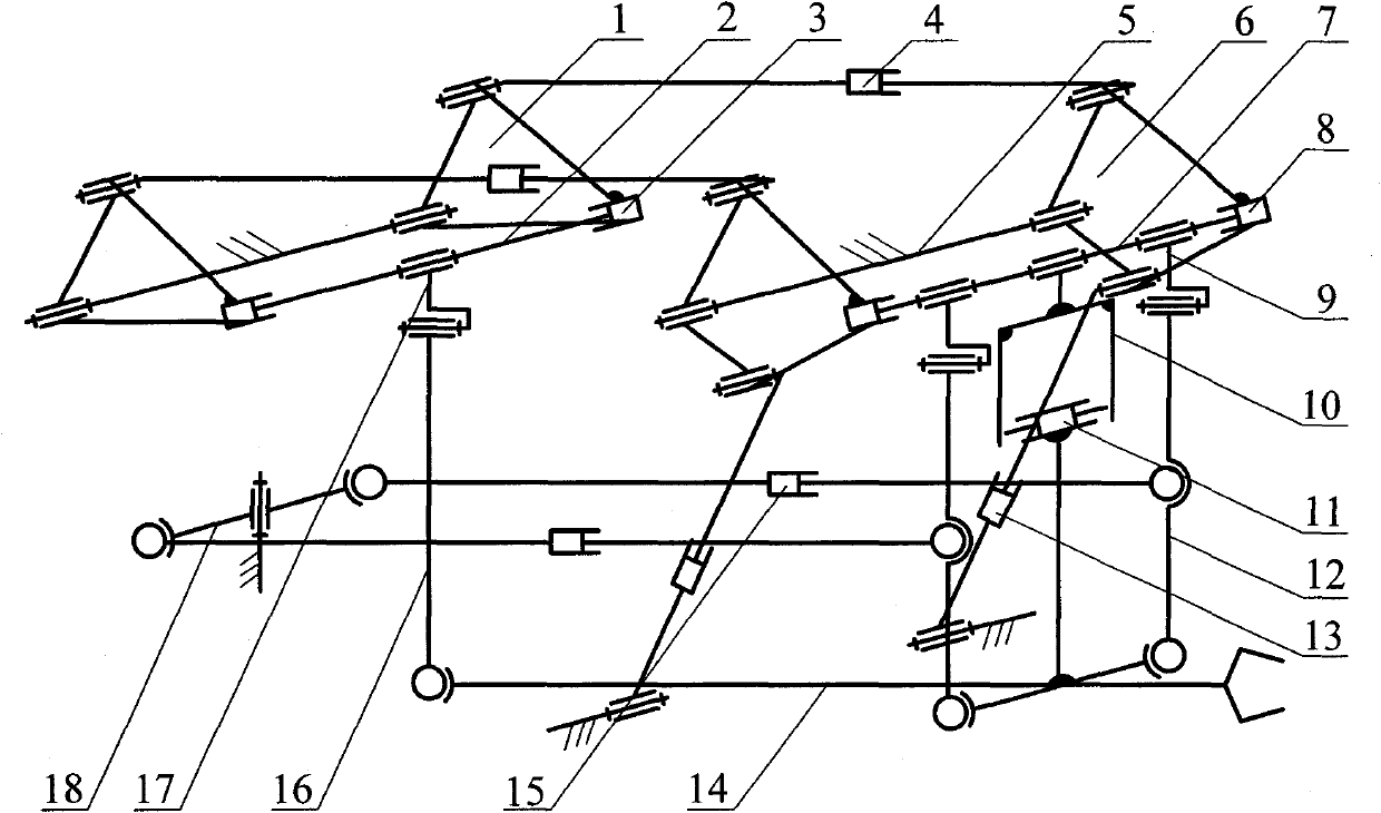
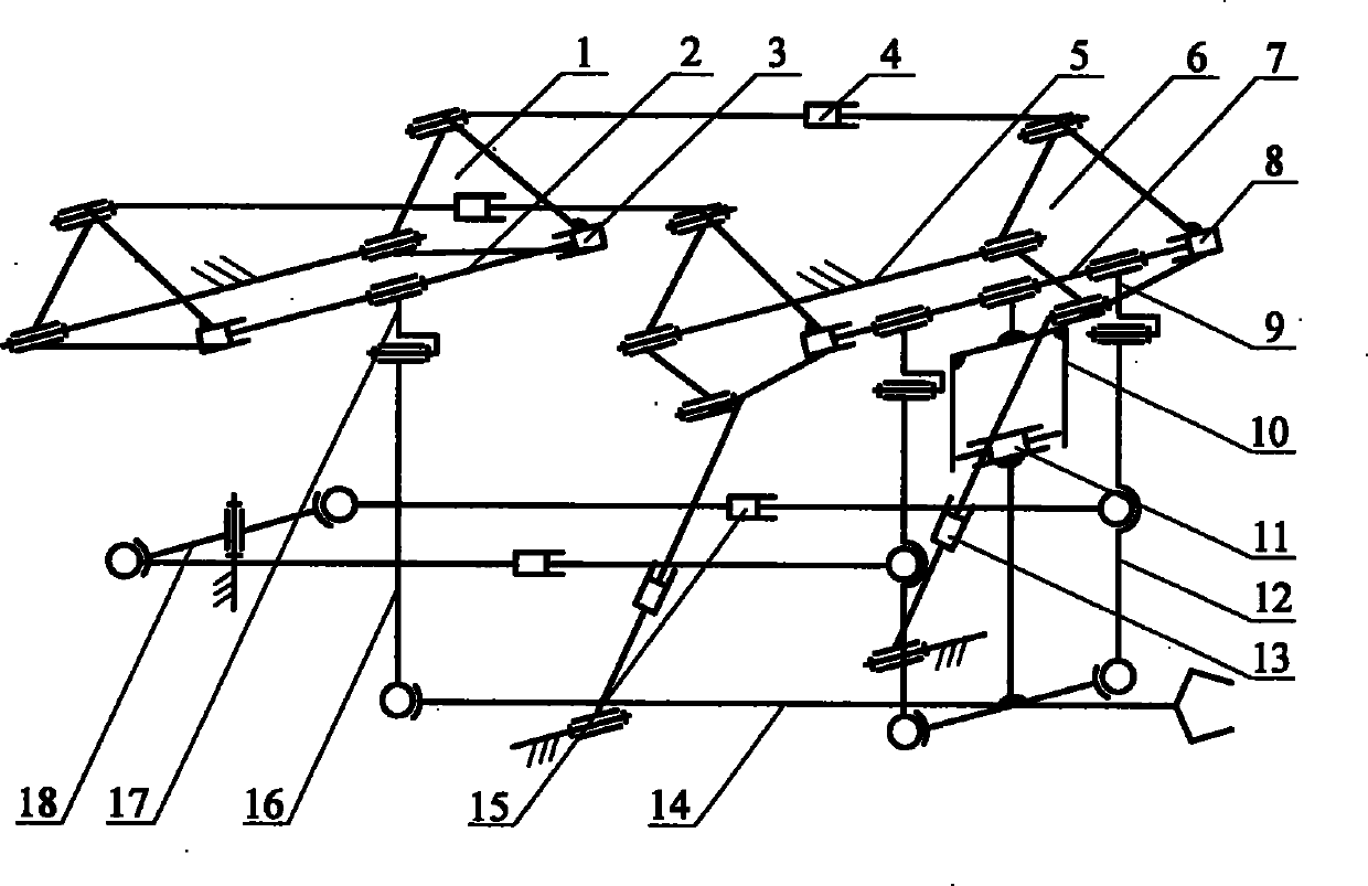
[0015] As shown in the drawings, this embodiment includes: a lifting device, a swing device, a front and rear buffer device, a left and right buffer device, a pincer rod 14 and a frame 5, wherein the swing device is installed on the upper part of the lifting device, and the pincer rod 14 is installed on the lifting device. At the bottom of the device, the front end of the front and rear buffer devices is connected to the front suspension rod 12 middle part of the lifting device, and the rear end is connected with the frame 5, and the left and right buffer devices are i...


PUM


Abstract

The invention relates to a lifting mechanism of a forging manipulator in the mechanical engineering technical field. The lifting mechanism is characterized in that the upper ends of two front suspension rods (12) are separately connected with the lower ends of two front connecting parts (9) through swivel hinges arranged in the front-back horizontal direction of axes, the lower ends are separately connected with the left and right sides of the front part of a claw beam (14) through spherical hinges, the upper end of a back suspension rod is connected with the lower end of a back connecting rod (17) through a swivel hinge arranged in the front-back horizontal direction of axis, the connecting parts (9) and the back connecting part (17) are separately connected with a front sliding rod (7) and a back sliding rod (2) through swivel hinges arranged in the left-right horizontal direction of axes; and two pitching linear drivers (4) are horizontally arranged in the front and back of the top of a lifting arm, the front ends of the drivers are separately connected with the two sides of a front lifting arm (6) through swivel hinges, and the back ends are separately connected with the two sides of a back lifting arm (1) through swivel hinges. The invention is characterized in that the installation is convenient, the structure is simple, and the forging quality of forgings is easy to ensure.

Description

technical field [0001] The invention relates to a device in the technical field of mechanical engineering, in particular to a lifting mechanism of a forging manipulator used for free forging. Background technique [0002] The forging manipulator is one of the basic tools for large-scale forging pressure processing, and it is used in conjunction with the press. Generally speaking, the forging manipulator needs to realize seven forging operation functions including jaw clamping, tong bar rotation, tong bar lifting, tong bar pitching, tong bar lateral movement, tong bar swing, and cart travel. Among them, the three actions of jaw clamping, clamp rod rotation, and cart walking are independent from each other in structure, and are respectively driven by motors or hydraulic pressure. The clamp realizes the clamping and rotating functions of the workpiece, and the cart undertakes the traveling function. The action is realized by the lifting mechanism. [0003] After searching the...

Claims


Application Information

Patent Timeline
IPC IPC(8): B21J13/10
Inventor 赵永生许允斗姚建涛
Owner YANSHAN UNIV
Why Eureka
Try Eureka