
Protection switching device for lost control of crane and related control method

A technology of protection switch and control method, applied in safety devices, transportation and packaging, load hanging components, etc., can solve the problems of slow response of overspeed switches, easy damage, low speed of heavy objects falling, etc., to achieve a wide range of applications, design Ingenious, simple-structured effects

Inactive Publication Date: 2010-08-04
上海能港电气工程科技有限公司
View PDF4 Cites 13 Cited by
  • Summary
  • Abstract
  • Description
  • Claims
  • Application Information

AI Technical Summary

Problems solved by technology

[0004] However, after the failure of the potential energy system, the heavy object fell out of control, and the heavy object began to drive the rotation of the system shaft; The falling speed of the object is not high, and the rotation speed of the system shaft is not high, so the overspeed switch cannot recognize that the fault has occurred; When the braking device sends out an alarm signal, the moving speed of the heavy object lifted by the lifting system is extremely high at this time, and the braking torque and energy are both large (kinetic energy is proportional to the square of the speed), and the braking device is often overloaded. However, it is easy to damage and fail. Due to the limitation of the structure, the braking device of some systems can only brake the static load, but the dynamic load mechanism itself cannot satisfy the large impact. At this time, it will lead to major accidents, machine crashes
Therefore, the current lifting system, especially the heavy-duty lifting system, only relies on the safety protection device of the overspeed switch to be defective.

Method used


Image

  • Protection switching device for lost control of crane and related control method
  • Protection switching device for lost control of crane and related control method
  • Protection switching device for lost control of crane and related control method

Examples


Embodiment Construction

[0025] In order to understand the technical content of the present invention more clearly, the following examples are given in detail.

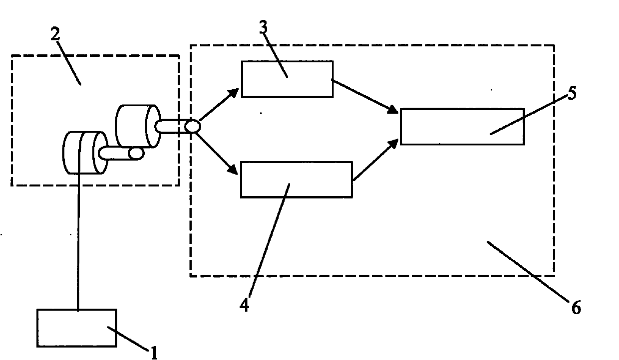
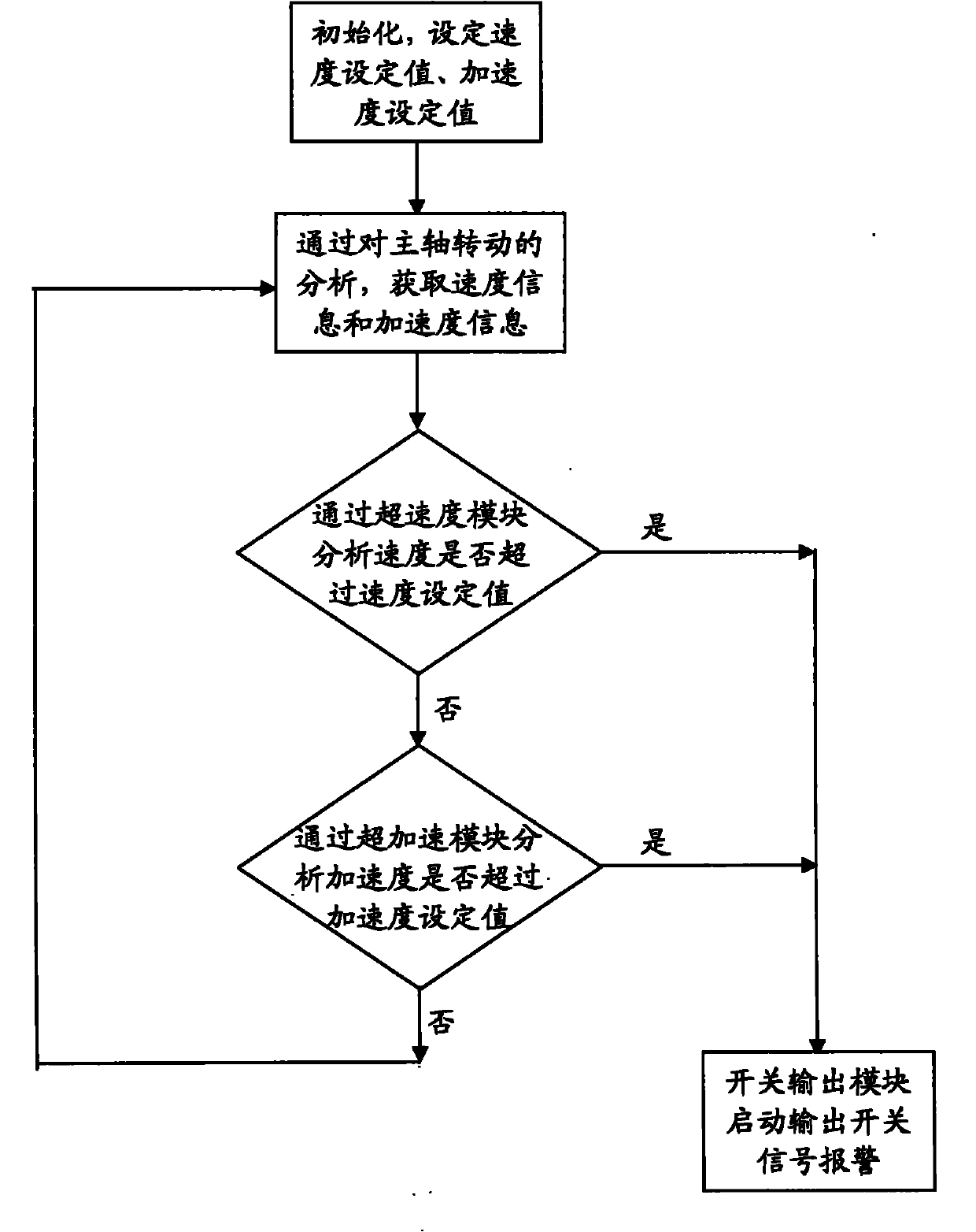
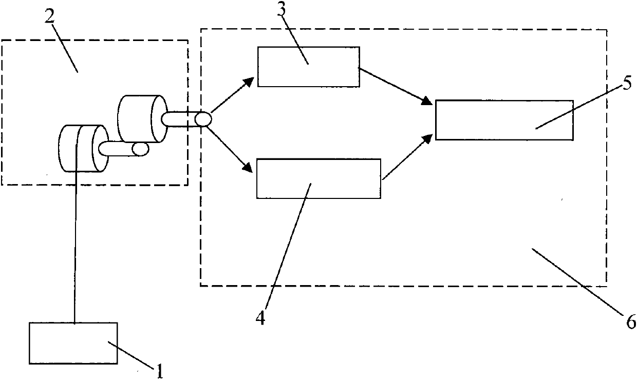
[0026] See figure 1 As shown, the crane runaway protection switch device 6 of the present invention includes an overspeed module 3, an overacceleration module 4 and a switch output module 5, and the overspeed module 3 and the overacceleration module 4 are respectively connected to the switch output module 5 , the super-speed module 3 is used to measure the speed of the hoisting object 1 and analyze whether the speed exceeds a preset speed setting value, and the super-acceleration module 4 is used to measure the acceleration of the hoisting object 1 and analyze the speed. Whether the acceleration exceeds the preset acceleration setting value, if the speed exceeds the speed setting value and / or the acceleration exceeds the acceleration setting value, the switch output module 5 starts to give an alarm.

[0027] Preferably, the displacement of t...


PUM


Abstract

The invention provides a protection switching device for lost control of a crane, which comprises a super-speed module, a super-acceleration module and a switching output module. The super-speed module and the super-acceleration module are connected with the switching output module respectively; the super-speed module is used for measuring the speed of a lifted object and analyzing whether the speed exceeds a preset speed setting value; the super-acceleration module is used for measuring the acceleration of the lifted object and analyzing whether the acceleration exceeds a preset acceleration setting value; and if the speed exceeds the speed setting value and / or the acceleration exceeds the acceleration setting value, the switching output module is started to alarm. The invention also provides a related control method. The protection switching device has the advantages of skilful design, simple structure, low cost, economy and practicability, quick response, safety and reliability, can effectively prevent the lost control of the crane, has the same effect on the potential energy load movement of other crane types such as an obliquely-pulled belt machine and a conveyor, and is suitable for large-scale popularization and application.

Description

technical field [0001] The invention relates to the technical field of a safety protection switch device for moving a potential energy load, in particular to the technical field of a crane safety protection switch device, in particular to a crane runaway protection switch device and a related control method. Background technique [0002] In daily industrial production and people's life, using mechanical equipment to move large objects and bulk goods is a very common motion control. How to effectively protect moving objects from possible out-of-control failures, especially for moving objects with potential energy, such as elevators , Cranes, cable-stayed belt conveyors and conveyors, etc., may appear to slide due to loss of control, making the object continuously accelerate and accumulate a large amount of momentum during the slide, making it difficult to brake and causing serious collision accidents. [0003] The current measuring device for the rotating shaft of the lifting...

Claims


Application Information

Patent Timeline
IPC IPC(8): B66C15/00B66C15/06B66C13/22
Inventor 何勤奋郑超张定军夏玉峰
Owner 上海能港电气工程科技有限公司
Learn More