Methods and systems for controlling engine shutdown in a vehicle

A technology of engine shutdown, engine, applied in the direction of engine starting, engine components, combustion engine

Active Publication Date: 2010-08-04
FORD GLOBAL TECH LLC
View PDF13 Cites 19 Cited by
  • Summary
  • Abstract
  • Description
  • Claims
  • Application Information

AI Technical Summary

Problems solved by technology

Instead, the engine may then be fully rev-down and utilize a restart from stop, which ma

Method used


Image

  • Methods and systems for controlling engine shutdown in a vehicle
  • Methods and systems for controlling engine shutdown in a vehicle
  • Methods and systems for controlling engine shutdown in a vehicle

Examples


Embodiment Construction

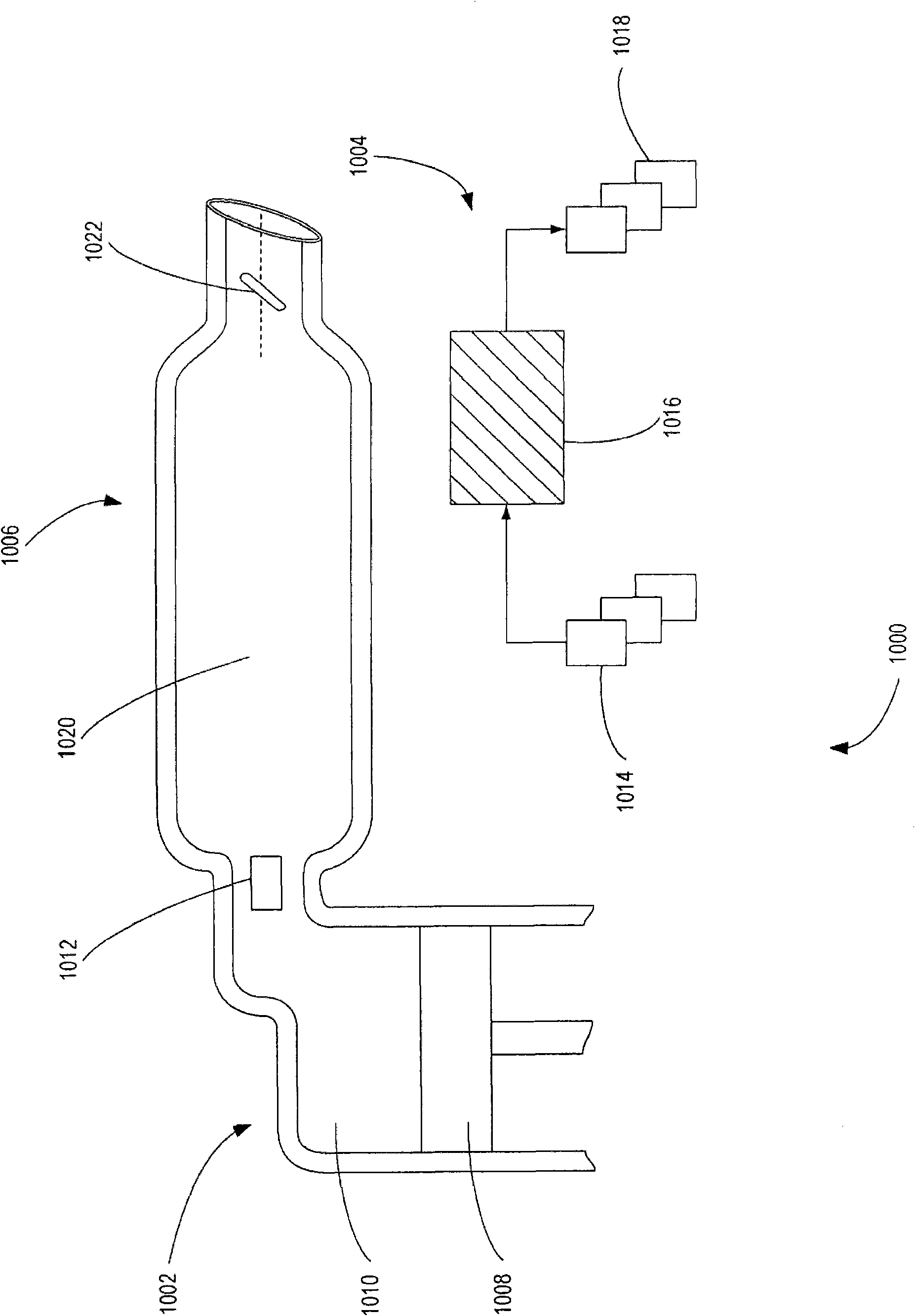
[0015] Figure 1A An engine system 1000 is depicted for controlling engine shutdown and engine restart after cessation of combustion and during engine speed drop. The engine system 1000 includes an engine cylinder 1002 connected to an engine control system 1004 , an intake conduit 1006 connected to the engine cylinder and the engine control system. In alternative examples, there may be more than one engine cylinder connected to the intake duct and engine control system.

[0016] Engine cylinder 1002 includes piston 1008 , combustion chamber 1008 and means for controlling air charge 1012 coupled between the combustion chamber and an intake conduit. The piston is drivable by combustion within a combustion chamber and is connectable to a crankshaft within a crankcase (not shown). Device 1012 may be in an open state, a partially open state, or a closed state. In some examples, device 1012 may be connected to control system 1004 . In this manner, device 1012 may control air flow...


PUM


Abstract

Methods and systems are provided for controlling engine shutdown in a vehicle. One example method includes, after discontinuation of combustion and during engine spin down, reducing cylinder air charge while maintaining intake manifold pressure above a threshold value.

Description

【Technical field】 [0001] The present invention relates to a method and system for controlling engine shutdown in a vehicle. 【Background technique】 [0002] During operation of a motor vehicle, it may be necessary to stop the vehicle for a period of time, for example at a traffic light (hereinafter "temporary stop"). Some vehicles can be run during a temporary stop by idling the engine within the engine system. Other vehicles can stop the engine (even without a driver request to shut down the engine) during temporary stops to reduce fuel consumption. For example, the vehicle may shut down the engine by shutting down the fuel supply and / or ignition to allow the engine speed to drop to a standstill. The engine can then be automatically restarted once conditions indicate that the driver intends to start the vehicle. [0003] One example method of controlling engine stopping during such a temporary stop is described in US Patent 4,515,124. This patent describes a system and a...

Claims


Application Information

Patent Timeline
IPC IPC(8): F02D41/06F02D9/02F02D41/30
CPCF02N19/00F02N99/006Y02T10/42F02D2041/001F02N2300/2002Y02T10/48F02D41/0002F02N2200/022F02N11/0844F02D41/042Y02T10/40
Inventor A·O·吉布森
Owner FORD GLOBAL TECH LLC
Why Eureka
Try Eureka