Design method of single-vane stamping type non-clogging impeller

A design method, stamping technology, applied in mechanical equipment, non-variable-capacity pumps, components of pumping devices for elastic fluids, etc., to achieve good non-clogging performance.

Inactive Publication Date: 2010-08-04
JIANGSU GUOQUAN PUMP MFG CO LTD
View PDF0 Cites 28 Cited by
  • Summary
  • Abstract
  • Description
  • Claims
  • Application Information

AI Technical Summary

Problems solved by technology

[0004] In order to solve the above problems, the present invention provides a single-blade stamping type non-clogging impeller design method, the single-blade stamping non-clogging impeller designed by the present invention has good non-clogging performance and high efficiency; the geometric parameters can meet the needs of the impeller stamping process

Method used


Image

  • Design method of single-vane stamping type non-clogging impeller
  • Design method of single-vane stamping type non-clogging impeller
  • Design method of single-vane stamping type non-clogging impeller

Examples


Embodiment

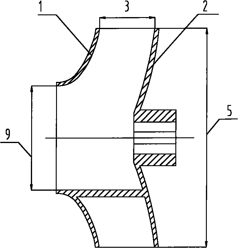
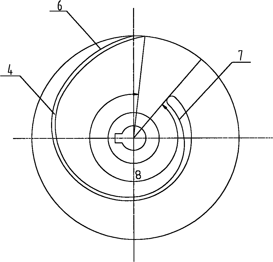
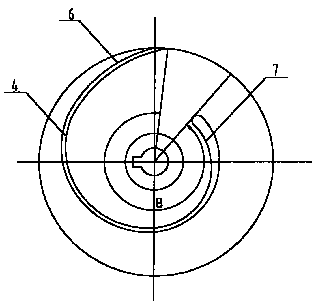
[0030] figure 1 and figure 2 Together determine the impeller shape for this embodiment. Like most single-blade non-clogging impellers, it has an impeller front cover (1) and an impeller rear cover (2), which is a closed impeller. If there is no impeller front cover plate and impeller rear cover plate very little, promptly make semi-open impeller and open impeller, also do not influence enforcement of the present invention. In the figure, the convex surface of the blade (4) is the blade working surface (6), the concave surface of the blade (4) is the blade back (7), the impeller inlet diameter (9) in the present embodiment, the impeller outlet width (3), The outer diameter of the impeller (5) is obtained according to the following relational formula.

[0031] Impeller inlet diameter D 0 The calculation formula is: D 0 = K 0 (Q / n) 1 / 3 K 0 =3.5~4.0

[0032] Impeller outer diameter D 2 The calculation formula is: D 2 = ...


PUM


Abstract

The invention relates to a design method of a single-vane stamping type non-clogging impeller. Compared with the single-vane non-clogging impellers designed by the traditional methods, the single-vane non-clogging impeller designed by the invention has high non-clogging performance and efficiency and can meet the requirement of stamping process for the geometric parameters of the impeller.

Description

technical field [0001] The invention relates to a method for designing the main parts of a non-variable pump, in particular to a method for designing a single-blade punching type non-clogging impeller. Background technique [0002] Non-clogging pump impellers are mainly divided into ordinary single (double) vane type, swirl type, single (double) channel type, and screw centrifugal pump type. The single-blade non-clogging pump impeller has high efficiency, stable operating conditions, and processing The production cost is low. At present, the design method of single-blade non-clogging impeller mainly has the following two problems: 1. The non-clogging performance of the designed non-clogging impeller is poor, and it cannot meet the requirements of high non-clogging performance for conveying fluids; 2. When the impeller design meets the non-clogging performance requirements , the efficiency of the impeller drops a lot. Due to the existence of design problems, the single-blad...

Claims


Application Information

Patent Timeline
Patent Type & Authority Applications(China)
IPC IPC(8): F04D29/22
Inventor 朱荣生胡自强杨爱玲付强
Owner JIANGSU GUOQUAN PUMP MFG CO LTD
Why Eureka
Try Eureka