Multiple blade type non-blocking pump and impeller thereof

A non-clogging pump and multi-blade technology, which is applied in the field of sewage conveying equipment and slurry, can solve the problems of poor anti-winding performance, large hydraulic loss, and increased cost, and achieve good passability and anti-fiber winding performance, anti-winding and Good non-clogging performance, improved efficiency and lift

Inactive Publication Date: 2014-08-13
JIANGSU UNIV
View PDF11 Cites 5 Cited by
  • Summary
  • Abstract
  • Description
  • Claims
  • Application Information

AI Technical Summary

Problems solved by technology

Single- and double-channel pumps are suitable for transporting fluids with large particles and long fibers. Since the number of blades of single-channel pumps is one, the blades cannot be symmetrically arranged, and the balance is poor. The noise and vibration are relatively large when the pump is running; double-channel pumps The balance is slightly better than that of single-channel pumps, but the blades are thicker than ordinary centrifugal blades, and the anti-winding is poor. It is easy to cause blockage when conveying slender fibers, causing the pump to not work normally, and even burning the motor.
The impeller of the swirl pump is generally retracted in the back pump chamber of the volute, the blade is a simple straight blade shape, the pump inlet diameter is small, the outer diameter of the impeller to the volute inlet area is narrow, and the long fiber and large particle solids are conveyed When the medium is used, it is easy to cause blockage, and the blades are straight blades with large hydraulic loss and low efficiency. When this type of pump is running, the power is easily overloaded in the large flow area and the motor will be burned.
[0004] After retrieval, the published patent "Impeller and non-clogging swirl pump for non-clogging swirl pump" (Application No.: 201220259153.4) has a straight blade shape, and the impeller retracts into the rear pump chamber, so the efficiency is low , and the high-efficiency area is easily overloaded
The diameter of the pump inlet is small, and more long-fiber and large-particle solid media enter the impeller, causing a certain degree of wear and blockage of the impeller; the published patent "a non-clogging crushing pump with open impeller" (application number: 201120437821.3), It installs a cutter disc for cutting impurities such as large particles and long fibers at the inlet of the pump, but the structure of the pump becomes complicated and the cost increases when the cutter disc device is installed, and the cutter disc consumes part of the power when the pump is running, resulting in The efficiency, head and flow rate of the pump are reduced, and the installation of the cutter disc at the pump inlet itself reduces the effective passage area of ​​the pump, reduces the passage capacity of the pump, and causes a certain degree of blockage

Method used


Image

  • Multiple blade type non-blocking pump and impeller thereof
  • Multiple blade type non-blocking pump and impeller thereof
  • Multiple blade type non-blocking pump and impeller thereof

Examples


Embodiment Construction

[0018] The present invention will be further described in detail below in conjunction with the accompanying drawings and specific embodiments: These accompanying drawings are all simplified schematic diagrams, and only illustrate the basic structure of the present invention in a schematic manner.

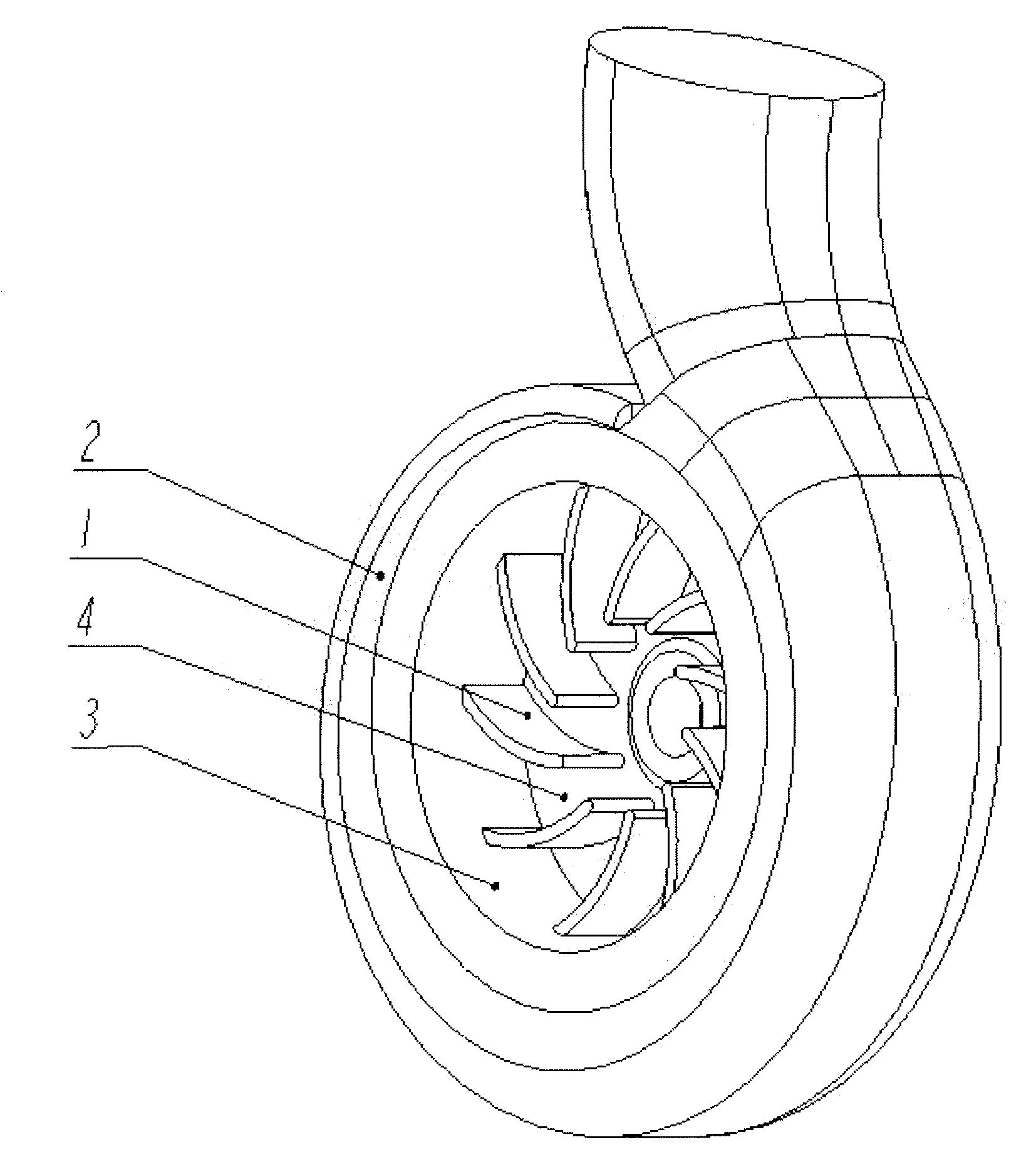
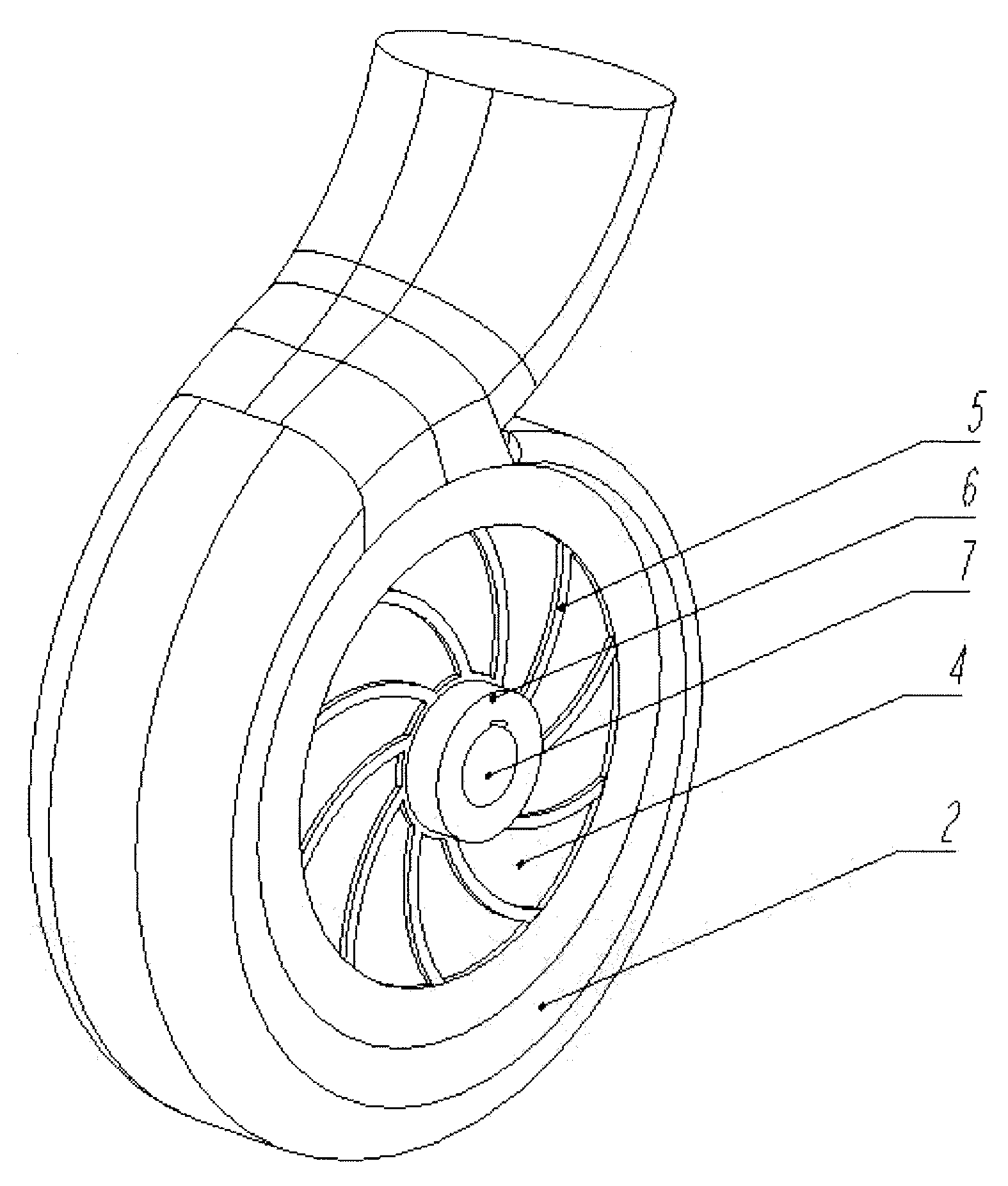
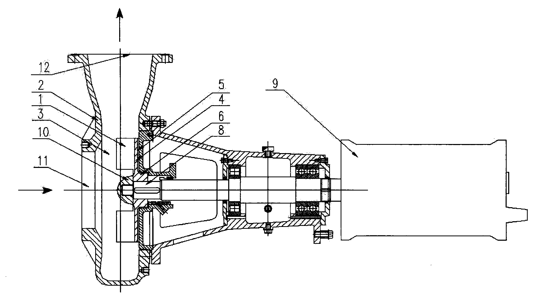
[0019] figure 1 , figure 2 Volute and impeller for multi-vane non-clogging pumps, image 3 It is a multi-vane non-clogging pump, which mainly includes vane (1), volute (2), vaneless chamber (3), rear cover plate (4), auxiliary vane (5), wheel body (6), shaft hole (7), pump shaft (8), motor (9), shaft end nut (10), pump inlet (11), pump outlet (12). The impeller is fixed on the pump shaft through the shaft end nut. The pump shaft is connected with the driving motor shaft and installed in the volute. When the motor rotates, the pump shaft drives the impeller to rotate, which can realize slurry, sewage medium or gas-containing medium. delivery.

[0020] The impeller of the preferr...


PUM


Abstract

The invention relates to a multiple blade type non-blocking pump and an impeller thereof. The multiple blade type non-blocking pump comprises a pump body, the impellers, a pump shaft and a driving motor. The pump body is characterized in that an inlet of the pump is designed into a large inlet, the impellers are placed on one side of the interior of a pump cavity, and the width of a portion of the cavity, which does not contain the impellers, is 0.15-0.20 of the outer diameter of each impeller. The impeller comprises a wheel body, a wheel shaft at the center of the wheel body, and a blade and a subsidiary blade on the wheel body. The impeller is set in a half open multiple blade type, only comprises a rear cover plate (2) and does not comprise front cover plate. The impellers of the multiple blade type non-blocking pump are different from impellers of a common non-blocking pump, wherein the number of the impellers of the common non-blocking pump is small, and inlet and outlet placement angles of the impellers of the common non-blocking pump are all 90 degrees, and inlet and outlet placement angles of the impellers of the multiple blade type non-blocking pump are all less than 90 degrees, and furthermore the inlet diameter Dj of each impeller of the multiple blade type non-blocking pump is small. According to the multiple blade type non-blocking pump and the impeller thereof, not only is impact loss on inlet areas of the impellers reduced, but also the effective work area of the impellers for mediums is increased, and furthermore vortex loss on the inlet areas of the impellers is reduced, and therefore efficiency and head coefficients are increased. The size of the inlet of the multiple blade type non-blocking pump is about 1.2 times of the size of an inlet of the common non-blocking pump, and accordingly the size of the portion of the cavity, which does not contain the impellers, is as small as possible on the premise of not influencing passage capacity, not only are the efficiency and the head coefficients increased, but also a majority of long fiber and large particle solid bodies can directly enter a spiral case not through the impellers, and furthermore twine-resistant and non-blocking performances of the multiple blade type non-blocking pump are good.

Description

technical field [0001] The invention relates to a multi-vane non-clogging pump and its impeller, in particular to a non-clogging pump impeller mainly suitable for transporting solids with entangled long fibers and large particles, or transporting fluid medium containing part of gas. The utility model belongs to the technical field of slurry and sewage conveying equipment. Background technique [0002] At present, when conveying pulp, sewage and sewage media, the pump is often clogged due to solid impurities such as long fibers such as long plastic fibers, hemp fibers, pulp fibers and large particles in the medium, which affects the passing performance and performance of the pump. The operating efficiency reduces the reliability and service life of the pump; the fibers wrapped around the impeller not only reduce the effective flow area of ​​the pump and cause blockage, but also require frequent shutdowns for processing and frequent maintenance, which affects work efficiency a...

Claims


Application Information

Patent Timeline
Patent Type & Authority Applications(China)
IPC IPC(8): F04D29/22F04D29/24F04D29/42
CPCF04D29/2244
Inventor 高雄发施卫东张启华张德胜程成
Owner JIANGSU UNIV
Why Eureka
Try Eureka