Congestion control system

A technology of control device and limiting part, which is applied in program control design, transmission system, telephone communication, etc. It can solve the problems of high load of blocking control function and inability to provide blocking control function, etc., and achieve the effect of high-speed data synchronous processing

Inactive Publication Date: 2010-08-04
HITACHI LTD
View PDF1 Cites 6 Cited by
  • Summary
  • Abstract
  • Description
  • Claims
  • Application Information

AI Technical Summary

Problems solved by technology

[0005] Since the load given to the synchronization server is different for each state of the request, the content of the state change blocking control corresponding to the request is effective (see, for example, L. Massoulie and J. Roberts, "Arguments in favor of admission control for TCP FLOWS ", ITC 16, 1999), but when analyzing the received request to judge the state, the load on the congestion control function is very high when the request is concentrated, and the congestion control function cannot be provided

Method used


Image

  • Congestion control system
  • Congestion control system
  • Congestion control system

Examples


Embodiment 2

[0091] The second embodiment is such an embodiment: that is, when the congestion control device, that is, the relay device, restricts the relay of the request according to the load level included in the request from the terminal 102, the next request from the terminal 102 Load rating reduced.

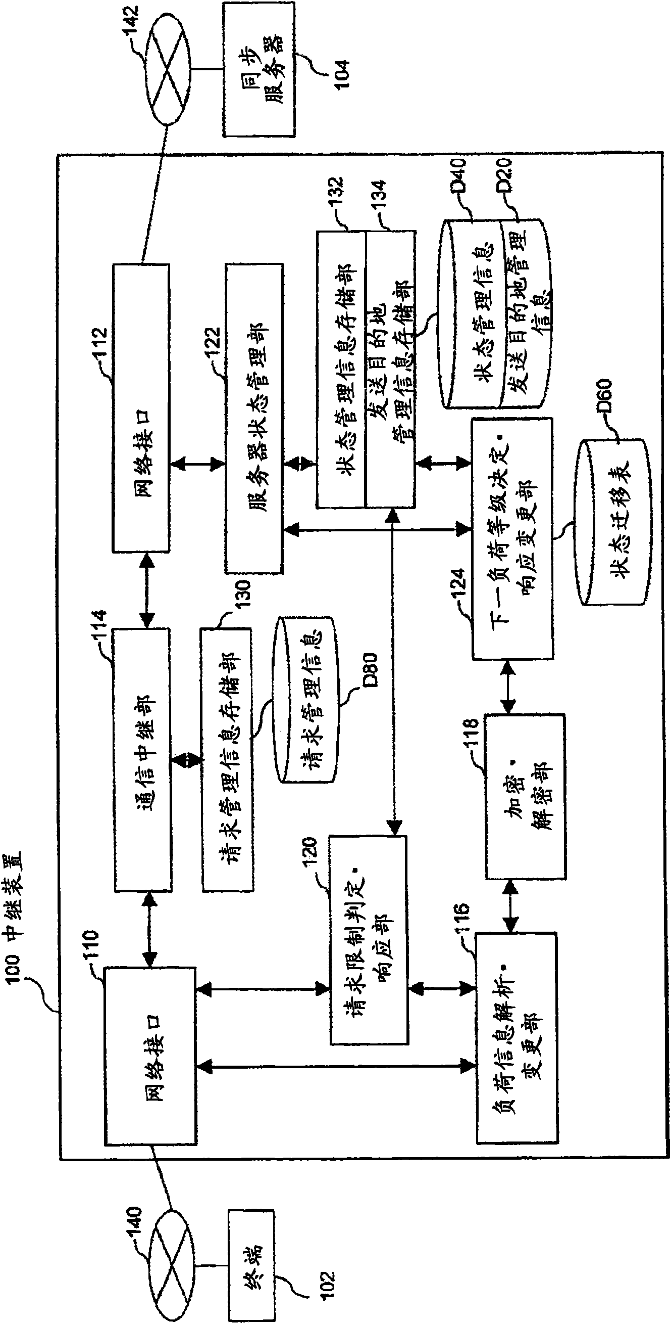
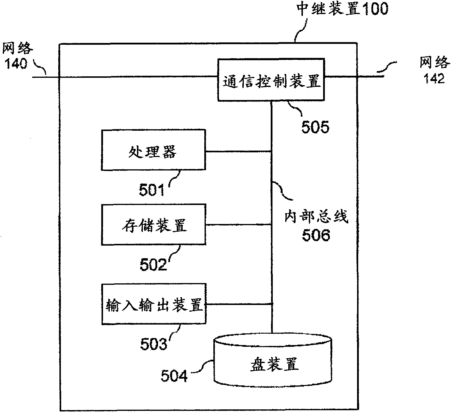
[0092] Figure 14 A configuration example of the communication system of the second embodiment is shown. The relay device 100 -B includes a response URI creation unit 128 that creates a response URI to be used in the request URI of the next request from the terminal 102 . Other configurations are the same as those of the relay device 100 of the first embodiment. The same applies to the point that the processor 501 executes a program, cooperates with each device as necessary, and realizes each processing unit at the same time.

[0093] The flowchart showing the detailed operation when the relay device 100-B of the second embodiment receives a request from the terminal 102 is similar t...

Embodiment 3

[0098] The third embodiment is an embodiment in which HTTP cookies are used in the exchange of load information between the terminal 102 and the relay device 100, which is the congestion control device, and the relay of requests is restricted using the load information.

[0099] Figure 16A configuration example of the communication system of the third embodiment is shown. The relay device 100-C includes: a Cookie analysis / deletion unit 136 that analyzes and deletes the HTTP header field "Cookie" included in the request from the terminal 102; In response, the next load level determination / cookie addition unit 138 adds information on the load level as the HTTP header field "Set-Cookie". Other configurations may be the same as those of the relay device 100 according to the first embodiment. The same applies to the point that the processor 501 executes a program, cooperates with each device as necessary, and realizes each processing unit at the same time.

[0100] Figure 17 ...

Embodiment 4

[0106] The fourth embodiment is an embodiment in which the relay device 100 which is the congestion control device delays the relay of the request to the server device for a certain period of time according to the value of load information included in the request from the terminal 102 . In this embodiment, since the relaying of the request is not rejected, no restriction response is returned.

[0107] Figure 18 A configuration example of the communication system of the fourth embodiment is shown. The relay device 100-D includes a relay delay unit 150 that holds the relay of the request to the synchronization server 104 for a certain period of time. Other configurations are the same as those of the relay device 100 of the first embodiment. In addition, the same applies to the point that the processor 501 executes a program, cooperates with each device as necessary, and realizes each processing unit at the same time.

[0108] The flowchart showing the detailed operation when...


PUM


Abstract

A congestion control system is provided between a terminal (102) and a server device to avoid a congestion state in the server device by preferentially regulating the request with a high load on the server device. The congestion control system estimates the load of the request from the terminal (102) to be placed on the server device for the next communication sequence, based on the response from the server device to the request from the terminal, and adds the estimated load information to the response to the terminal (102). Subsequently, the request from the terminal includes the load information, so that the congestion control system controls the regulation of the request from the terminal based on the load information included in the request.

Description

technical field [0001] The present invention relates to a congestion control function of a device installed on a communication path of a terminal in a network system such as WWW (World Wide Web) in which data communication is performed between a server device and a terminal. Background technique [0002] Due to the popularization of portable terminals, there is an increasing demand for data synchronization such as schedule tables among multiple terminals such as mobile phones and PCs. In addition, it is expected that with the improvement of terminal performance in the future, the need for synchronization of large-capacity content such as photos and animations will also increase. These data synchronizations are performed by coordinating data synchronization processing with a synchronization server installed in the middle. However, it can be expected that as the demand for data synchronization increases, the load imposed on the data synchronization server will increase sharply...

Claims


Application Information

Patent Timeline
Patent Type & Authority Applications(China)
IPC IPC(8): H04L12/56H04L29/06H04M3/00H04L47/80
CPCH04L67/2828H04L29/08963H04L67/2819H04L29/08747G06F9/505H04L29/08783H04L67/325H04L67/02H04L29/0809H04L67/564H04L67/5651H04L67/62
Inventor 相乐恭宏木下雅文
Owner HITACHI LTD
Why Eureka
Try Eureka