Check patentability & draft patents in minutes with Patsnap Eureka AI!

Turbomolecular pump

A technology of turbomolecular pumps and rotors, applied in pumps, pump components, axial flow pumps, etc., can solve problems such as reducing the life of rolling bearings, and achieve the effects of reducing heat generation and stress reduction

Inactive Publication Date: 2010-08-04
OERLIKON LEYBOLD VACUUM
View PDF0 Cites 5 Cited by
  • Summary
  • Abstract
  • Description
  • Claims
  • Application Information

AI Technical Summary

Problems solved by technology

This causes mechanical stresses in the components involved and thus greatly reduces the life of the rolling bearings

Method used


Image

  • Turbomolecular pump
  • Turbomolecular pump

Examples


Embodiment Construction

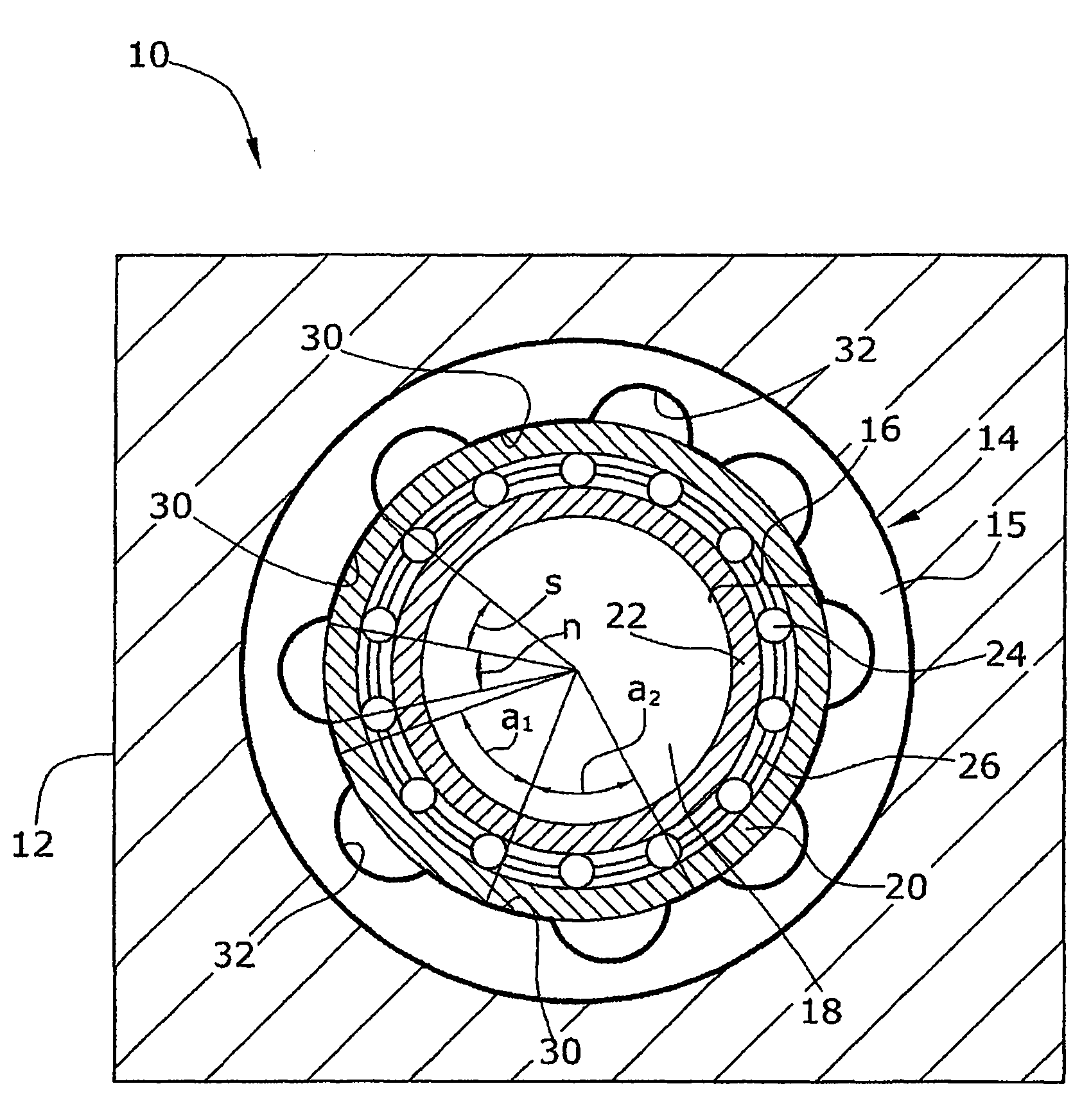
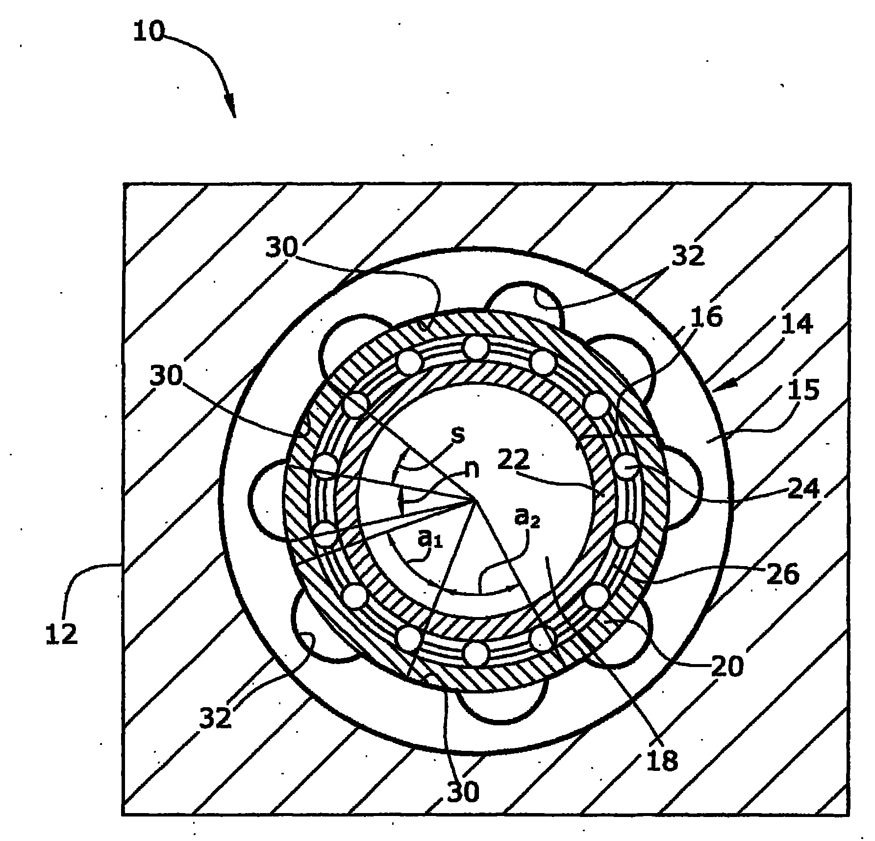
[0016] The figure shows a turbomolecular pump 10 operating at a rated rotational speed well above 10,000 U / min.

[0017] The turbomolecular pump 10 has a housing 12 , on which a rolling bearing 16 is mounted by means of a vibrating ring 14 , and the rolling bearing 16 carries a rotor 18 . The rolling bearing 16 has an outer non-rotating bearing shell 20 , an inner rotating bearing shell 22 , rolling elements 24 and a rolling element cage 26 .

[0018] The vibrating ring 14 is formed integrally from an elastomer and has an anisotropic shape on its circumference. The vibrating ring 14 consists of a plastic body 15 which is formed continuously closed on the housing side in the circumferential direction. The vibrating ring 14 has eight support points 30 distributed irregularly over its circumference, which are formed in the form of radially inner support islands. The fulcrums 30 or support islands 30 are separated from one another by axial grooves 32 which are circular in cross ...


PUM


Abstract

The invention relates to a turbomolecular pump (10) having a rotor (18) which is mounted on a housing (12) by means of at least one rolling bearing (16). The rolling bearing (16) has a non-rotating bearing shell (20) and a rotating bearing shell (22). The non-rotating bearing shell (20) is mounted on the housing (12) by means of an elastic vibration ring (14). The vibration ring (14) is of anisotropic design, such that the spring stiffness is non-uniform over the periphery.

Description

technical field [0001] The invention relates to a turbomolecular pump with a rotor mounted on a housing via at least one rolling bearing, wherein the rolling bearing is mounted on the housing by means of an elastic vibrating ring. Background technique [0002] The turbomolecular pump operates at a high speed exceeding 10,000 U / min. Vibrations in the transmission of a turbomolecular pump, and especially in the bearings, can generate heat, which can cause sudden and rapid heat loss in the bearings not only during continuous operation at a constant speed, but also during a drop in speed or during an increase in speed. A temperature rise occurs. This causes mechanical stresses in the components involved and thus greatly reduces the service life of the rolling bearing. [0003] It is common in turbomolecular pumps to support the rolling bearing in a vibrating ring, which elastically suspends the rolling bearing within a narrow range relative to the housing. This makes it possi...

Claims


Application Information

Patent Timeline
IPC IPC(8): F04D19/04F04D29/66F04D29/059F04D29/056
CPCF16C27/066F04D29/668F04D29/0563F04D19/042F04D29/059F16C2360/45
Inventor 赖纳·赫尔策
Owner OERLIKON LEYBOLD VACUUM
Features
  • R&D
  • Intellectual Property
  • Life Sciences
  • Materials
  • Tech Scout
  • Unparalleled Data Quality
  • Higher Quality Content
  • 60% Fewer Hallucinations
Learn More