Puncture needle siliconization machine and siliconization process using same

A puncture needle and silicification technology, which is applied in the field of medical machinery, can solve problems such as long working hours, unguaranteed quality, and poor workmanship, and achieve the effects of increasing production, solving long working hours, and improving the quality of silicification

Inactive Publication Date: 2013-05-15
贝恩医疗设备(广州)有限公司
View PDF0 Cites 0 Cited by
  • Summary
  • Abstract
  • Description
  • Claims
  • Application Information

AI Technical Summary

Problems solved by technology

[0003] In view of the above problems, the present invention provides a puncture needle siliconization machine and a siliconization process using the siliconization machine, which solves the technical problems of long working hours, poor craftsmanship, and no guarantee of quality in the prior art.

Method used


Image

  • Puncture needle siliconization machine and siliconization process using same
  • Puncture needle siliconization machine and siliconization process using same

Examples


specific Embodiment 1

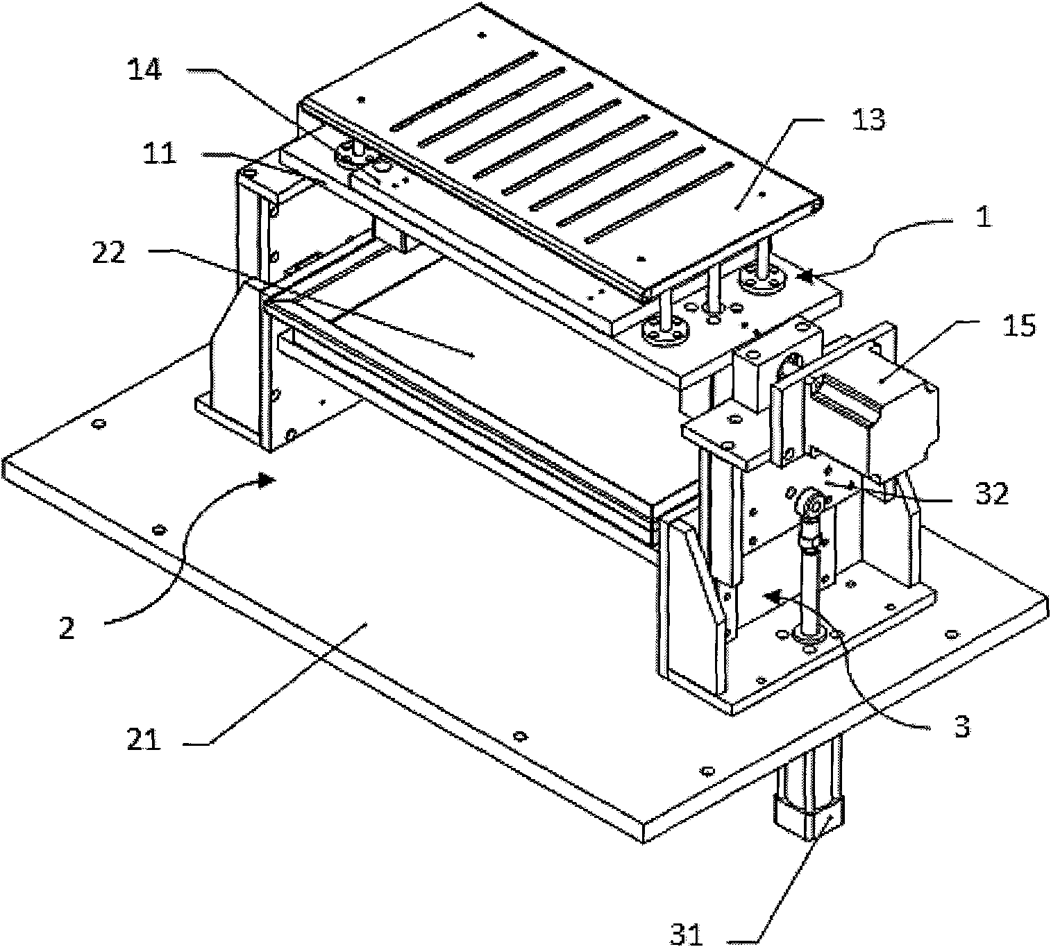
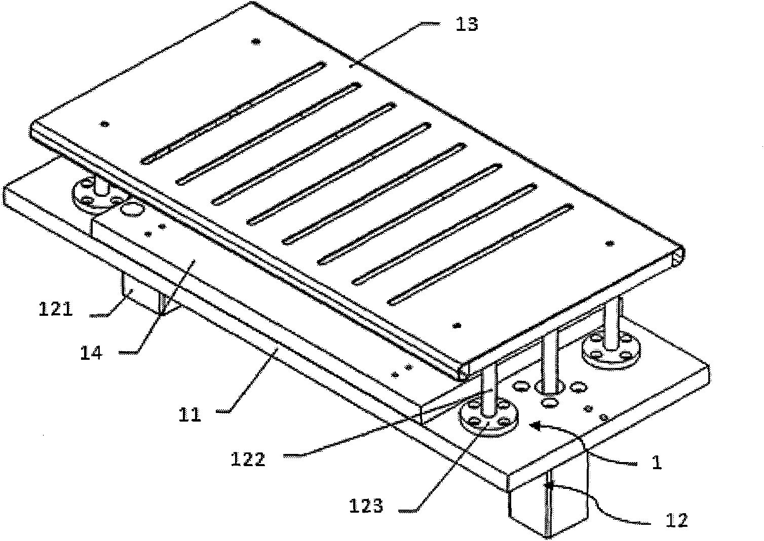
[0028] Such as figure 1 and figure 2 As shown, a puncture needle siliconization machine includes a needle device 1, a siliconization tank device 2 and a slide plate device 3. The needle device 1 includes an air guide plate 11 for blowing air to the puncture needle, and is installed on the air guide plate 11. The sliding assembly 12 at both ends and the needle presser 13 that fixes the needle plate 14, the sliding assembly 12 passes through the air guide plate 11, and its top is fixedly connected with the needle presser 13 and drives the needle presser 13 to move up and down; the siliconization pool device 2 includes a base 21 supporting the entire siliconization machine device and a silicone oil pool 22 installed on the base 21; the top end of the slider device 3 is fixedly connected to both ends of the needle device 1, and the bottom end is correspondingly fixed to both ends of the base 21 of the siliconization machine device .

[0029] The silicification process using the...

specific Embodiment 2

[0043] The difference between this embodiment and the specific embodiment 1 is that the sliding plate device 3 of the siliconization machine includes a solenoid valve device installed at both ends of the base 21 and an upper and lower sliding plate 32 for controlling the movement track of the solenoid valve device. The sliding assembly 12 of the needle device 1 includes a solenoid valve guide rod installed at both ends of the air guide plate and a solenoid valve to control its movement. The top end of the solenoid valve guide rod passes through the air guide plate 11 and is fixedly connected to the needle presser plate 13 .

specific Embodiment 3

[0044] The difference between this embodiment and the specific embodiments 1 and 2 is that the sliding plate device 3 of the siliconization machine includes the upper and lower cylinders 31 installed at both ends of the base 21 and the upper and lower sliding plates 32 for controlling the trajectory of the upper and lower cylinders 31 . The sliding assembly 12 of the needle device 1 includes a solenoid valve guide rod installed at both ends of the air guide plate and a solenoid valve to control its movement. The top end of the solenoid valve guide rod passes through the air guide plate 11 and is fixedly connected to the needle presser plate 13 .


PUM


Abstract

The invention discloses a puncture needle siliconization machine and a siliconization process using the same, which belong to the technical field of medical devices. The puncture needle siliconization machine comprises a needle device, a siliconization pool device and a sliding plate device, wherein the needle device comprises an air guide plate which is used for blowing the punctual needle, sliding components arranged at the two ends of the air guide plate and a needle pressure plate which fixes a needle plate; the sliding components pass through the air guide plate and the tops of the sliding components are fixedly connected with the needle pressure plate and the sidling components drive the needle pressure plate to move vertically; the siliconization pool device comprises a base supporting the whole siliconization machine and a silicon oil bath arranged on the base; and the top end of the sliding plate device is fixedly connected with the two ends of the needle device, while the bottom end is correspondingly fixed at the two ends of the base of the siliconization machine. The products assembled by the machine and the process have the advantages of high quality, high yield and low assembly cost.

Description

【Technical field】 [0001] The invention belongs to the technical field of medical machinery, and in particular relates to a fully automatic siliconization machine and a siliconization process using the siliconization machine. 【Background technique】 [0002] Puncture needles are widely used in medical devices in clinical medicine. Since the puncture needles directly enter the human body, in order to minimize the tingling sensation for users, it is necessary to coat the surface of the needles with a layer of silicone oil. At present, manual methods are used in silicification, that is, manually holding the needle, manually applying silicone oil, and manually blowing air. In this way of operation, the working hours are long, the workmanship is poor, the quality is not guaranteed, and the products produced cannot meet the quality requirements. With the continuous increase of market demand, this production mode can no longer meet the market demand, and also causes a lot of waste o...

Claims


Application Information

Patent Timeline
Patent Type & Authority Patents(China)
IPC IPC(8): B05C3/10B05C11/00B05C11/06B05C13/02B05D1/18
Inventor 廖磊
Owner 贝恩医疗设备(广州)有限公司
Why Eureka
Try Eureka