Deburring system for framework-containing rubber sealing ring

A technology for rubber sealing rings and deburring, which is applied in the field of sealing ring manufacturing, can solve problems such as difficulty in guaranteeing roundness, flatness, surface finish, non-compliance with requirements in the shape and position tolerance of sealing ring products, and easy deformation, etc. Reliability, reduce labor intensity, and ensure the effect of sealing effect

Pending Publication Date: 2019-01-04
扬中市佳阳氟塑有限公司
View PDF14 Cites 0 Cited by
  • Summary
  • Abstract
  • Description
  • Claims
  • Application Information

AI Technical Summary

Problems solved by technology

[0002] There are generally two ways to remove burrs from traditional injection molded parts. The first method is manual removal. As the name suggests, it is to manually remove burrs one by one with a knife. Although it is simple and easy to do, it is difficult to ensure roundness, flatness and surface finish. , and the work efficiency is extremely low
[0003] In recent years, a kind of sealing ring deburring equipment has appeared. The principle is to first freeze the burrs on the sealing ring with liquid nitrogen to make them brittle, and then put the brittle sealing ring into a rotary centrifuge. Fine sand, the brittle rubber burr on the sealing ring is removed by rotating the equipment with fine sand medium, but this method is suitable for the sealing ring without skeleton, if the sealing ring contains a rigid skeleton, it is easy to deform during the deburring process , so that the shape and position tolerance of the sealing ring product does not meet the requirements

Method used


Image

  • Deburring system for framework-containing rubber sealing ring
  • Deburring system for framework-containing rubber sealing ring
  • Deburring system for framework-containing rubber sealing ring

Examples


Embodiment Construction

[0025] The technical solutions of the present invention will be described in further detail below in conjunction with the accompanying drawings and specific embodiments.

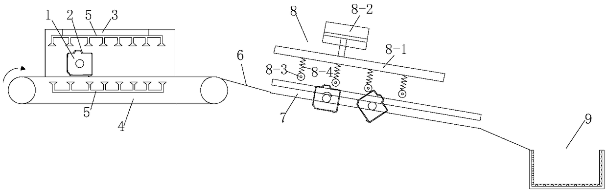
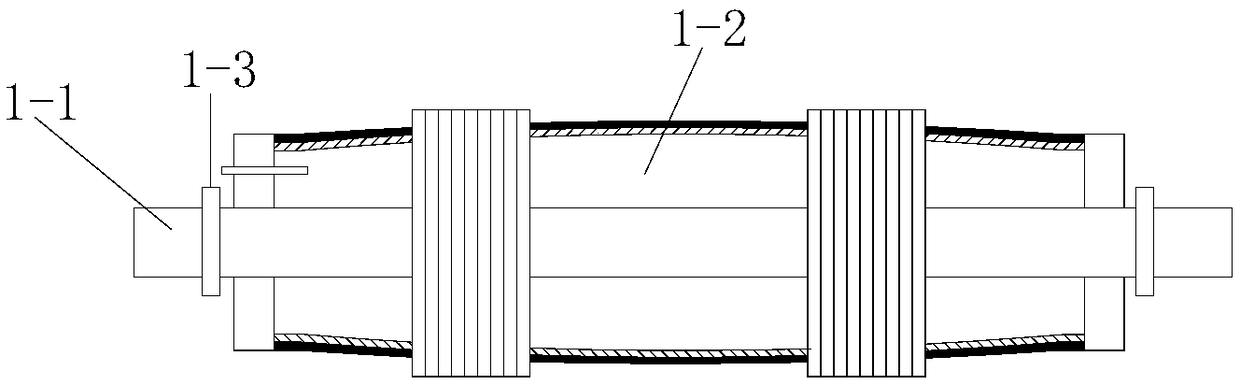
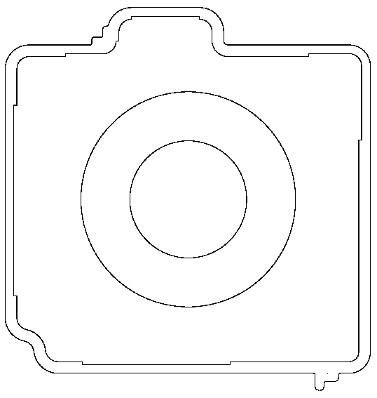
[0026] Such as figure 1 As shown, a rubber seal ring deburring system containing a skeleton includes a sleeve rod 1, which is used to socket and fix the seal ring 2 to be processed on the sleeve rod 1. The sleeve rod 1 includes: a rigid core rod 1 with a circular cross section -1, and the diameter reducing mechanism 1-2 arranged on the outside of the rigid core rod 1-1, the diameter reducing mechanism 1-2 supports and fixes the seal ring to be processed after expansion and diameter reduction, A bristle layer is provided on the surface of the contacting side of the circle;

[0027] The tunnel-type quick-freezing machine 3 includes: a tunnel cavity, the two ends of the tunnel cavity are respectively provided with a feed inlet and a discharge outlet, the bottom of the tunnel cavity is provided with a conveyor ...


PUM


Abstract

The invention discloses a deburring system for a framework-containing rubber sealing ring. The deburring system comprises a sleeve rod, a tunnel type quick-drying machine, a slideway, a core bar roller and a pre-pressing elastic deburring mechanism, wherein the sleeve rod is sleeved by a plurality of sealing rings to be treated; the tunnel type quick-drying machine comprises a tunnel cavity; a feeding hole and a discharge hole are respectively formed in both ends of the tunnel cavity; a conveyer belt is arranged at the bottom of the tunnel cavity; quick-drying liquid ejection holes are positioned on the upper side and the lower side of the conveyer belt; one end of the slideway is connected with the discharge hole of the tunnel type quick-drying machine; the other end of the slideway is arranged in a manner of being inclined downwards; the inlet of the core bar roller is connected with the tail end of the slideway; the other end of the core bar roller is arranged in the manner of beinginclined downwards; the pre-pressing elastic deburring mechanism comprises a top rack; the top rack is arranged above the core bar roller and is parallel to the core bar roller; a plurality of pre-pressing elastic deburring units are arranged at intervals at the bottom of the top rack in the rolling direction of the core bar roller. By adopting the deburring system, burr can be efficiently removed on the basis that an automobile driving cover plate sealing ring is not deformed.

Description

technical field [0001] The invention discloses a sealing ring burr removal system, which belongs to the field of sealing ring manufacturing. Background technique [0002] There are generally two ways to remove burrs from traditional injection molded parts. The first method is manual removal. As the name suggests, it is to manually remove burrs one by one with a knife. Although it is simple and easy to do, it is difficult to ensure roundness, flatness and surface finish. , and the work efficiency is extremely low. [0003] In recent years, a kind of sealing ring deburring equipment has appeared. The principle is to first freeze the burrs on the sealing ring with liquid nitrogen to make them brittle, and then put the brittle sealing ring into a rotary centrifuge. Fine sand, the brittle rubber burr on the sealing ring is removed by rotating the equipment with fine sand medium, but this method is suitable for the sealing ring without skeleton, if the sealing ring contains a rig...

Claims


Application Information

Patent Timeline
Patent Type & Authority Applications(China)
IPC IPC(8): B29C37/02
CPCB29C37/02
Inventor 朱创家朱小海
Owner 扬中市佳阳氟塑有限公司
Why Eureka
Try Eureka