Electric positioning impact wedging machine

An electric positioning and impact technology, applied in the field of die forging hammers in the mechanical field, can solve the problems of occupation, large hammer, large workshop area, etc., and achieve the effect of convenient use.

Active Publication Date: 2010-08-11
HUBEI TRI RING FORGING
View PDF0 Cites 0 Cited by
  • Summary
  • Abstract
  • Description
  • Claims
  • Application Information

AI Technical Summary

Problems solved by technology

The head of the wedge iron is small, but the ram is thick. Frequent and rapid repeated free swings and impacts make it impossible to locate and slightly eccentric. , causing personal injury
This kind of safety accident has occurred more than once; the second is that the actual use of the hammer is about two meters in length. To achieve a certain swing speed and generate sufficient impact force, it needs at least a swing distance of more than three meters. In this way, the die forging hammer There must be at least six meters of space behind, which will inevitably occupy a large workshop area

Method used


Image

  • Electric positioning impact wedging machine
  • Electric positioning impact wedging machine
  • Electric positioning impact wedging machine

Examples


Embodiment Construction

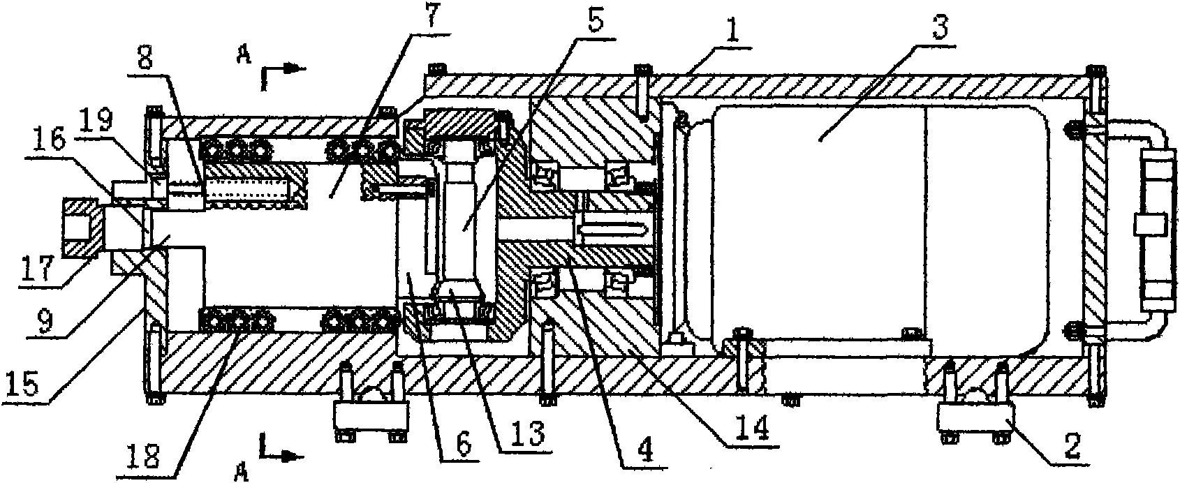
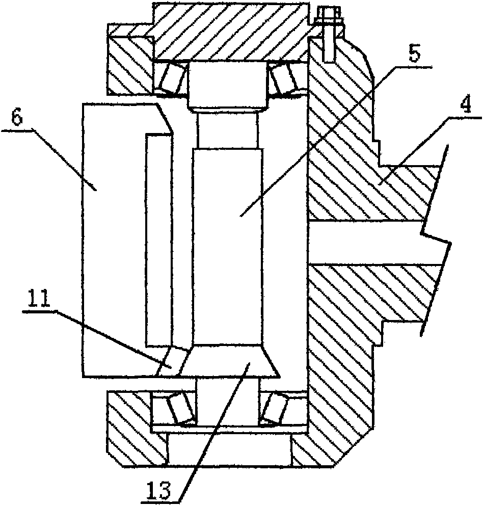
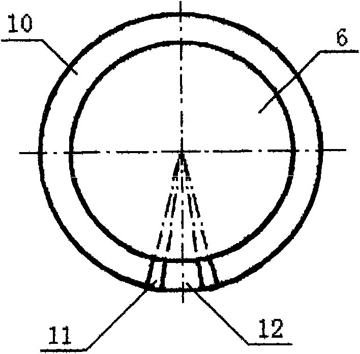
[0020] Such as Figure 1 to Figure 5 As shown, an electric positioning impact type wedge tightening machine is composed of a body 1, an impact mechanism, and a hoisting mechanism 2. The body 1 has a hoisting mechanism 2, and the body 1 has an impact mechanism. The impact mechanism consists of a motor 3, a pulley frame 4, The pulley shaft 5, the plane cam 6, the impact iron block 7, and the return spring 8 are composed of one end surface of the plane cam 6 with a smoothly connected in-situ conical surface 10, a spiral conical surface 11, and a raised conical surface 12, forming a continuous curved surface , the convex conical surface 12 is 5-10mm higher than the in-situ conical surface 10 in the axial direction, the angle of the spiral conical surface 11 on the end face circumference of the plane cam 6 is 9-18°, and the pulley shaft 5 is on the plane cam 6 The conical frustum 13 whose continuous curved surface angle matches, the pulley shaft 5 is connected with the pulley frame...


PUM


Abstract

The invention relates to an electric positioning impact wedging machine which overcomes the disadvantage that a ram is adopted originally to strike the fastening drill key of the forging hammer die of a wedging mould. The fastening drill key of the forging hammer die of the wedging mould can be positioned by the wedging machine in manner of adopting an electric impact technical scheme of an impaction mechanism mainly comprising an electromotor, a pulley yoke, a pulley shaft, a plane cam, an impact iron block and the like. The invention has the characteristics of small occupied work space, convenient use, safety, reliability and the like.

Description

technical field [0001] The invention relates to a die forging hammer in the mechanical field, in particular to a wedging device for fastening a wedge iron to a die of the die forging hammer. Background technique [0002] Die forging hammer is a large-scale general-purpose forging equipment widely used, and its working part is the forging hammer die, which is designed and manufactured according to the user's requirements, and then a structural part called fastening wedge iron is used to wedge the upper and lower dies respectively. Tightly on the hammer head and anvil of the die forging hammer. Due to the user's product replacement or grinding due to mold wear, the fastening wedge iron must be driven out and wedged in from time to time to disassemble and replace the upper and lower molds. Existing strike method all is to use swing free impact method, promptly is promoted by the people and hangs the ram, by swinging, strikes wedge iron and carries out. Although this method is...

Claims


Application Information

Patent Timeline
Patent Type & Authority Applications(China)
IPC IPC(8): B25B27/02
Inventor 胡道财张运军徐顺生邵光保陈天赋胡立国靳立平
Owner HUBEI TRI RING FORGING
Why Eureka
Try Eureka