Slice antenna and manufacturing method thereof

A manufacturing method and antenna technology, applied to antennas, electrical short antennas, antenna supports/mounting devices, etc., can solve the problems of unfavorable cost saving and complicated manufacturing process, and achieve the effect of convenient manufacturing method, low cost, and not easy to deform

Inactive Publication Date: 2010-08-11
FOXCONN (KUNSHAN) COMPUTER CONNECTOR CO LTD +1
View PDF0 Cites 4 Cited by
  • Summary
  • Abstract
  • Description
  • Claims
  • Application Information

AI Technical Summary

Problems solved by technology

However, such a production process is more complicated, which is not conducive to saving costs.

Method used


Image

  • Slice antenna and manufacturing method thereof
  • Slice antenna and manufacturing method thereof
  • Slice antenna and manufacturing method thereof

Examples


Embodiment Construction

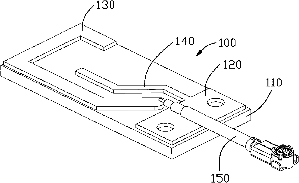
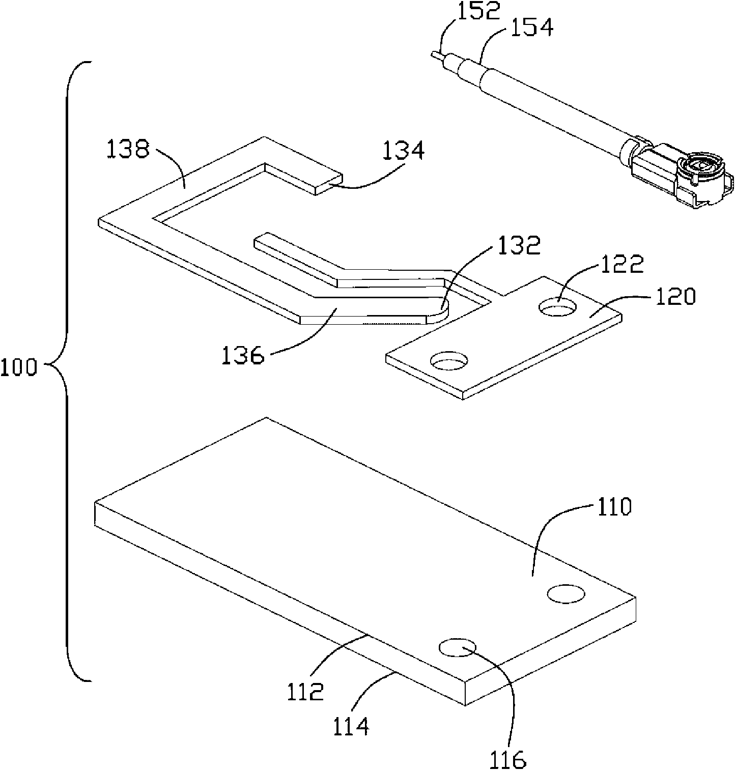
[0015] refer to figure 1 , figure 2 As shown, the chip antenna 100 in the figure is manufactured according to the antenna manufacturing method of the present invention. The chip antenna 100 includes a substrate 110 , a conductive foil (marked as a symbol) fixed on the substrate 110 , and a feeder 150 . The conductive foil is divided into two parts, including a ground part 120, a radiation part 130 set apart from the ground part 120, a parasitic metal arm 140 connected to the ground part 120 and separated from the radiation part 130, wherein the ground part 120 and the parasitic metal arm 140 is the first part, and the radiation part 130 is the second part. In this embodiment, the conductive foil is copper foil. In other embodiments, the conductive foil can be other metal foils, such as metal foils made of single metals such as gold, silver, aluminum, or metal foils formed by alloys. Conductive metals or their alloys are vapor-deposited, water-plated or coated on insulating...


PUM


Abstract

The invention discloses a slice antenna and a manufacturing method thereof. The slice antenna comprises a substrate, an electric conduction foil pasted on the substrate and a feeder line, wherein the electric conduction metallic foil can work at least on a first working frequency band, and the feeder line is welded on corresponding position on the metallic foil.

Description

【Technical field】 [0001] The present invention relates to a chip antenna and a manufacturing method thereof, in particular to a chip antenna installed inside an electronic device for wireless transmission and a manufacturing method thereof. 【Background technique】 [0002] Wireless communication functions have been increasingly integrated into modern electronic devices. As an essential component of wireless communication, antennas are increasingly used in electronic equipment. With the development of miniaturization and aestheticization of electronic equipment, and the advancement of antenna technology, more and more antennas are built into electronic equipment. Because of its small thickness and light weight, the sheet antenna has become a commonly used type of built-in antenna. However, since the sheet needs to fix the conductor sheet on the dielectric sheet to maintain a fixed antenna shape, the shape of the antenna may change due to deviations during the forming of the ...

Claims


Application Information

Patent Timeline
Patent Type & Authority Applications(China)
IPC IPC(8): H01Q1/14H01Q9/00H01Q13/08
Inventor 郑永昌
Owner FOXCONN (KUNSHAN) COMPUTER CONNECTOR CO LTD
Why Eureka
Try Eureka