

Drilling tool with drill bit
A technology of drilling tools and drill bits, which is applied in the direction of manufacturing tools, drilling/drilling equipment, parts of boring machines/drilling machines, etc. It can solve the problems of known drilling tools such as difficult operation, complicated manufacturing, and material weakening, and achieve simple The effect of interchangeability
- Summary
- Abstract
- Description
- Claims
- Application Information
AI Technical Summary
Problems solved by technology
Method used
Image

Examples
Embodiment Construction
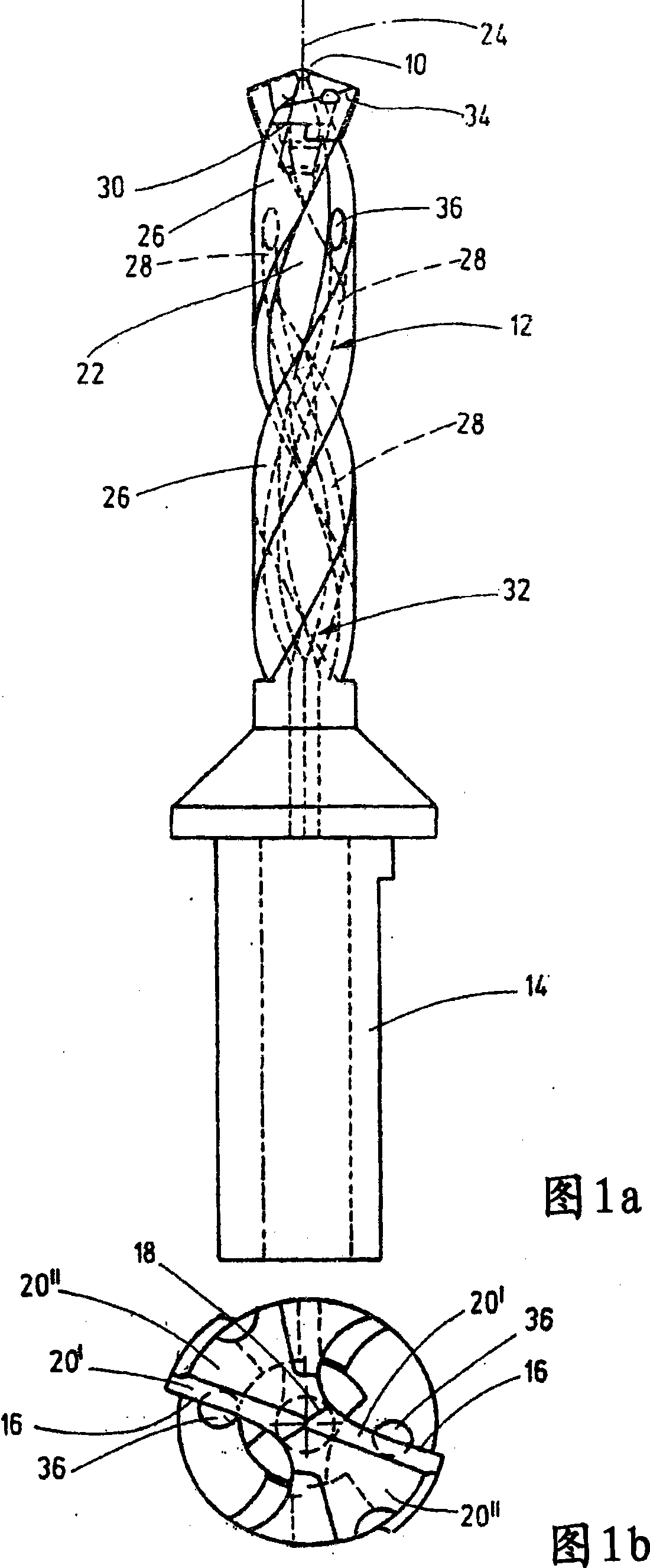
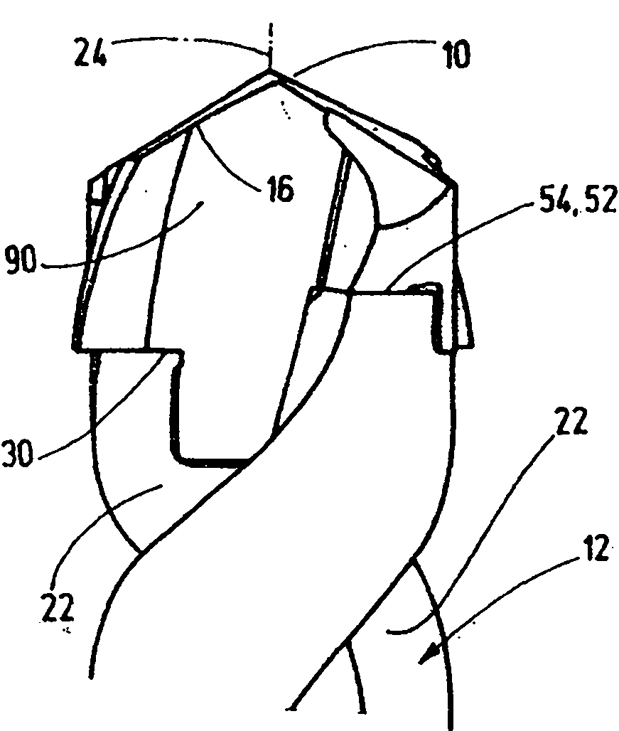
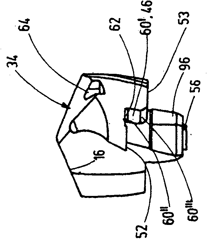
[0025] The drilling tool shown in the figures is divided into two parts at a separation point 30 and comprises a base body 32 with a shank 14 and a drill crown 34 with a drill tip 10 . The drill crown 34 and the base body 32 can be connected to one another in a form-fitting and force-fitting manner at the separation point 30 . The base body 32 is preferably made of tool steel or high-speed steel, while the drill crown 34 is constructed as a shaped part made of a cutting material selected from the group of cemented carbides or ceramics, which is produced and sintered as a sintered powder Injection molded parts or powder extrusion molded parts. In principle, the drill crown 34 can also be produced from tool steel coated with a wear-resistant layer.
[0026] Figure 1a to Figure 1cThe shown drilling tool has a drill tip 10 , a chip evacuation section 12 connected to the drill tip and a drill shank 14 formed behind the chip evacuation section 12 . The drill point 10 comprises t...
PUM
 Abstract
Description
Claims
Application Information