Motor-pump aggregate

一种电机泵、泵壳的技术,应用在泵、泵元件、机械设备等方向,能够解决高成本等问题,达到简化装配、平顺运转、简单制造的效果

Active Publication Date: 2010-08-11
CONTINENTAL AUTOMOTIVE TECH GMBH
View PDF1 Cites 14 Cited by
  • Summary
  • Abstract
  • Description
  • Claims
  • Application Information

AI Technical Summary

Problems solved by technology

Known diaphragm pumps generally do not meet these requirements due to vibrations or the high costs associated with sound / silencing measures

Method used


Image

  • Motor-pump aggregate
  • Motor-pump aggregate
  • Motor-pump aggregate

Examples


Embodiment Construction

[0053] Figure 1 to Figure 7 One embodiment of a motor-pump unit 101 is shown.

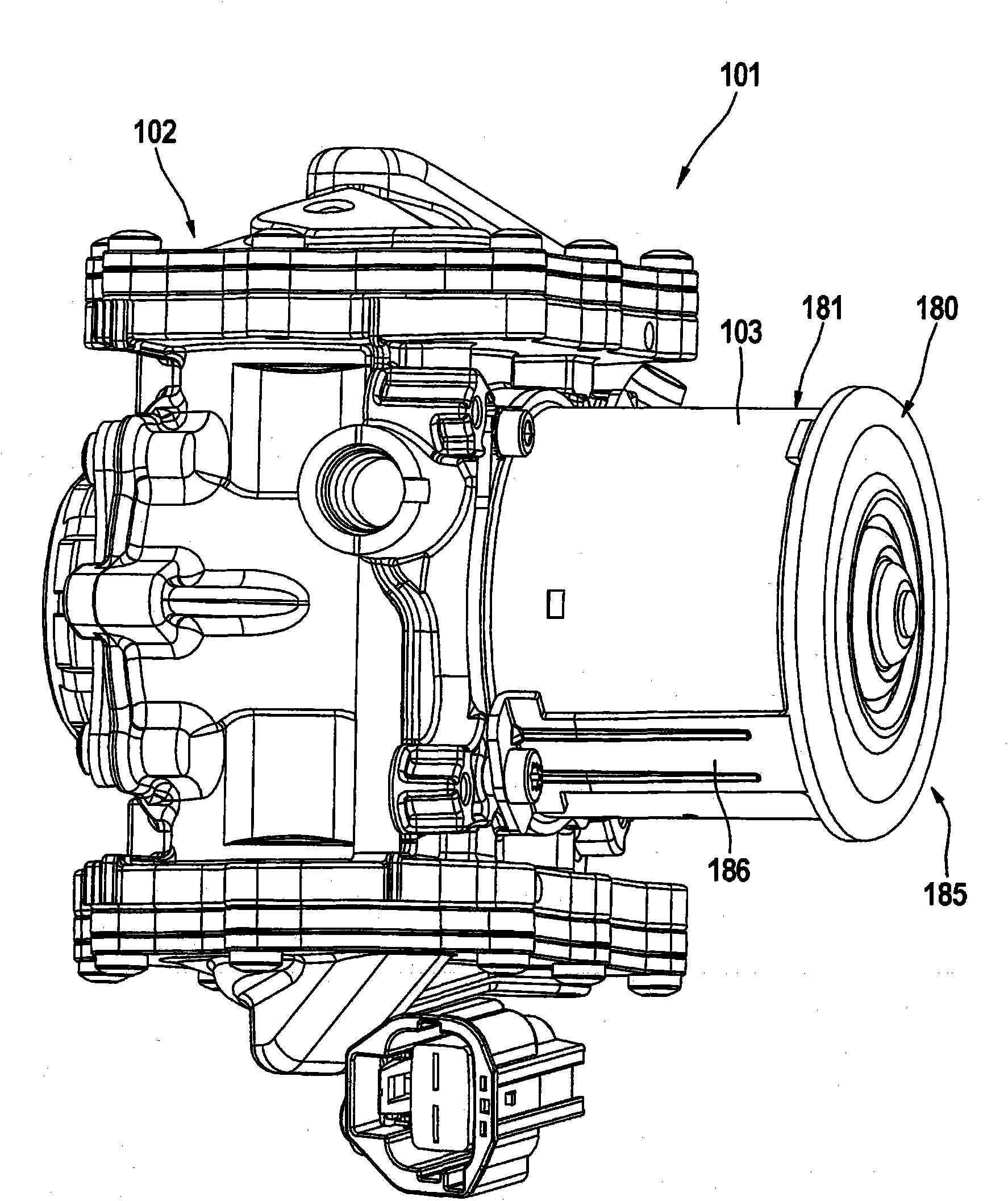
[0054] figure 1 A motor-pump assembly 101 is shown in perspective, comprising a pump 102 with a pump housing 105 and an electric motor 103 driving the pump 102 , wherein the electric motor 103 can be designed as a DC motor, for example.

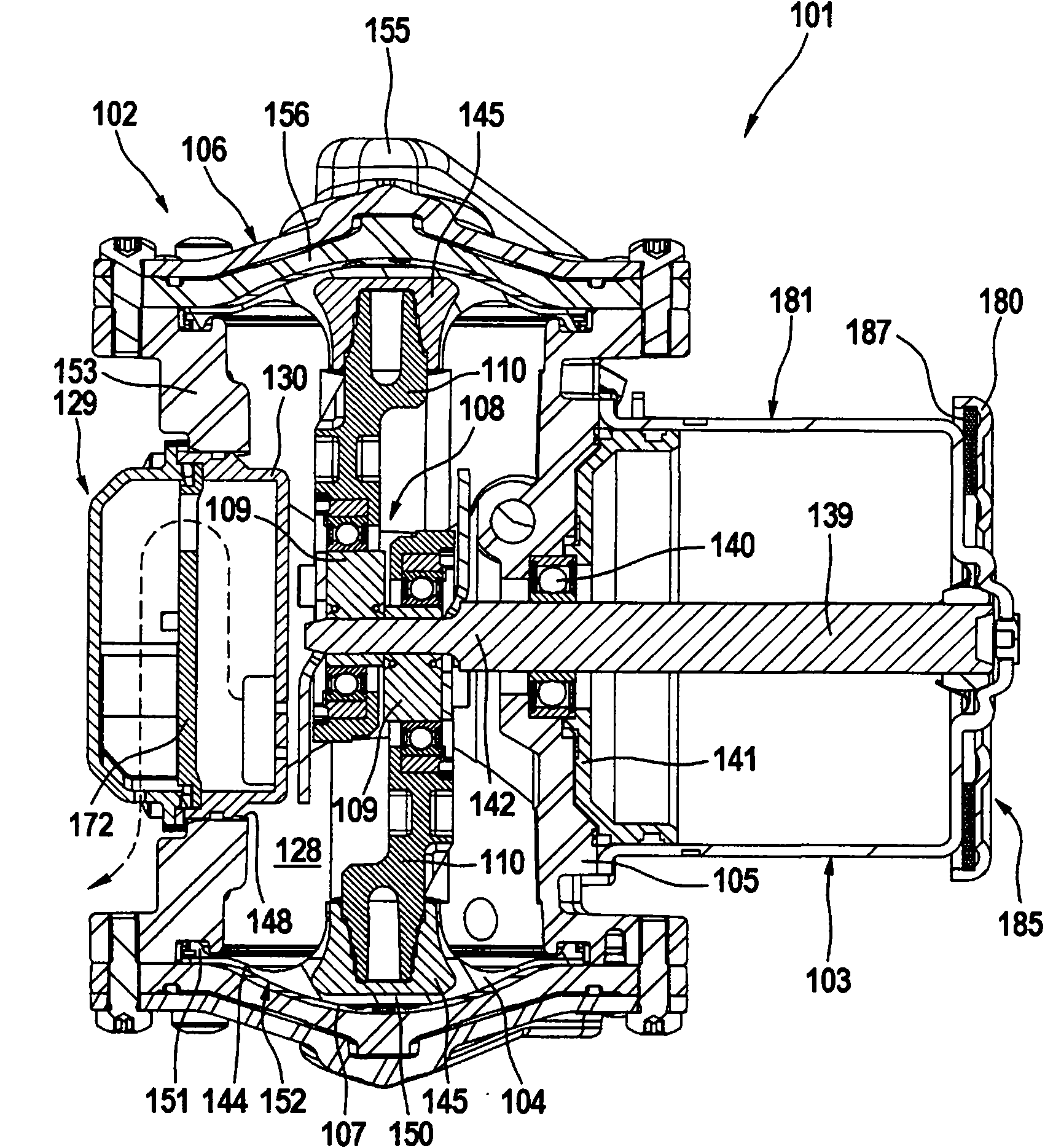
[0055] figure 2 The motor-pump unit 101 is shown in longitudinal section along a first plane, as figure 2 In particular, the pump 102 is shown as a double-diaphragm pump with two opposing working diaphragms 104 which are each tensioned between a pump housing 105 and a working chamber cover 106 and thus delimit a working chamber 107 . The working diaphragms 104 can be moved in the opposite direction by means of a crank drive 108 which includes an eccentric body 109 and a connecting rod 110 for each working diaphragm 104 .

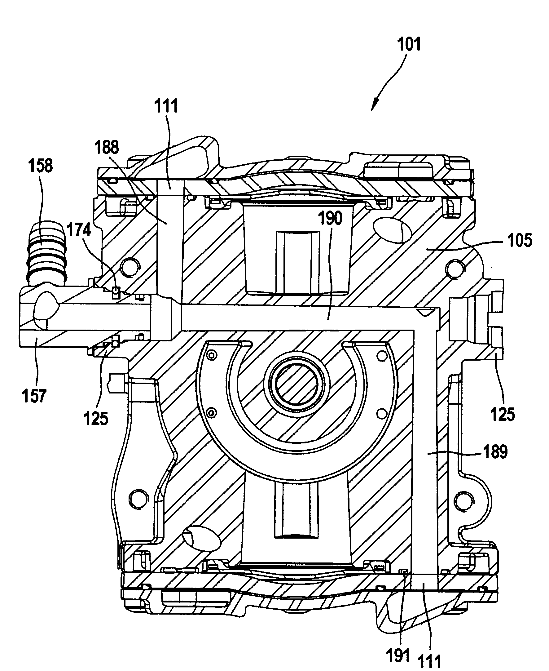
[0056] exist Figure 7 The working chamber cover 106 of the motor-pump unit 101 is shown in a sectional view. As can be seen from the...


PUM


Abstract

The invention relates to a motor-pump aggregate 101, particularly for providing pressure for a brake actuation device of a motor vehicle brake system having a pneumatic brake force amplifier, comprising a pump 102 and an electric motor 103 driving the pump 102, wherein the pump 102 is provided as a double-membrane pump having two opposing working membranes 104, each of which is clamped between a pump housing 105 and a working chamber cover 106, thereby bounding a working chamber 107, and which can be displaced by means of a crank drive 108 comprising an eccentric 109 and a connecting rod 110, the working chamber 107 being associated with one of each of an inlet channel 111 having an inlet valve 112, and an outlet valve 113 having an outlet valve 114. In order to provide a motor-pump aggregate comprising a dry-running pump and accommodating high standards with regard to acoustic comfort and service life, and being improved with regard to the pump efficiency thereof, the invention proposes that the outlet channels 113 be disposed in the working chamber covers 106 and in the pump housing 105 such that the air forced out of the working chambers 107 is guided into an inner chamber 128 of the pump housing 105 encompassing the crank drive, and that an air outlet unit 129 be provided that allows low-noise expulsion of the air from the inner chamber 128 by deflecting the air.

Description

technical field [0001] The present invention relates to a motor-pump assembly, in particular to a motor-pump assembly for providing pressure to a brake actuator of a motor vehicle braking system with a pneumatic brake booster (especially a vacuum brake booster), the assembly comprising A pump and an electric motor for driving the pump, wherein the pump is designed as a double-diaphragm pump with two opposing working diaphragms which are each tensioned between the pump housing and the working chamber cover and thereby delimit the working chamber , the diaphragm can be moved by a crank drive mechanism with an eccentric body and a connecting rod, wherein an intake channel with an intake valve and an exhaust channel with an exhaust valve are respectively assigned to each working chamber. Background technique [0002] A vacuum pump is used to provide a vacuum for the pneumatic brake booster, the inner cavity of which is divided into at least one vacuum chamber and a working chamb...

Claims


Application Information

Patent Timeline
Patent Type & Authority Applications(China)
IPC IPC(8): B60T17/00B60T17/02F04B39/00F04B43/04
CPCF04B39/0055F04B43/026F04B43/04B60T17/008B60T17/02F04B39/121B60Y2400/81B60Y2306/09
Inventor J·巴彻尔L·米利希奇W·里特尔K·塞茨M·吕费尔J·冈萨雷斯T·施塔尔M·于尔根宁Y·基安
Owner CONTINENTAL AUTOMOTIVE TECH GMBH
Why Eureka
Try Eureka