Check patentability & draft patents in minutes with Patsnap Eureka AI!

Spark ignition type internal combustion engine

A spark ignition, internal combustion engine technology, applied to internal combustion piston engines, combustion engines, mechanical equipment, etc., can solve problems such as no mention of content

Inactive Publication Date: 2013-03-13
TOYOTA JIDOSHA KK
View PDF3 Cites 0 Cited by
  • Summary
  • Abstract
  • Description
  • Claims
  • Application Information

AI Technical Summary

Problems solved by technology

However, the above-mentioned literature has no mention of this aspect

Method used


Image

  • Spark ignition type internal combustion engine
  • Spark ignition type internal combustion engine
  • Spark ignition type internal combustion engine

Examples


Embodiment Construction

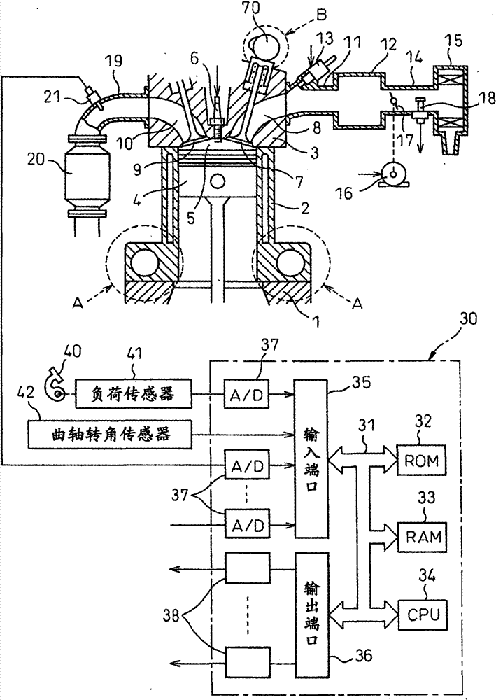
[0025] figure 1 A side sectional view showing a spark ignition internal combustion engine.

[0026] refer to figure 1 , Reference numeral 1 denotes a crankcase, 2 denotes a cylinder block, 3 denotes a cylinder head, 4 denotes a piston, 5 denotes a combustion chamber, 6 denotes a spark plug arranged at the central portion of the top surface of the combustion chamber 5, 7 denotes an intake valve, 8 Indicates the intake port, 9 indicates the exhaust valve, and 10 indicates the exhaust port. The intake port 8 is connected to a surge tank (surge tank) 12 through an intake branch pipe 11 , and a fuel injection valve 13 for injecting fuel into the corresponding intake port 8 is disposed on each intake branch pipe 11 . In addition, instead of attaching the fuel injection valve 13 to each intake branch pipe 11 , the combustion injection valve 13 may be arranged in each combustion chamber 5 .

[0027] Adjustment tank 12 is connected to air cleaner 15 through intake pipe 14 in which...


PUM


Abstract

In an internal combustion engine, a variable compression ratio mechanism (A) able to change a mechanical compression ratio and a variable valve timing mechanism (B) able to control the closing timing of an intake valve (7) are provided. The mechanical compression ratio is held at a maximum mechanical compression ratio at the engine low load operation side and gradually made to decrease as the engine load increases at the engine high load operation side. Combustion is performed by a stoichiometric air-fuel ratio at the engine high load operation side, and combustion is performed by a lean air-fuel ratio at the engine low load operation side where the mechanical compression ratio becomes the maximum mechanical compression ratio.

Description

technical field [0001] This invention relates to spark ignition internal combustion engines. Background technique [0002] A spark ignition type internal combustion engine is known (for example, refer to Japanese Patent Application Laid-Open No. 2004-218522 ): a variable compression ratio mechanism capable of changing the mechanical compression ratio and a variable valve timing mechanism capable of controlling the closing timing of the intake valve. Timing mechanism (variable valve train), and when the internal combustion engine is operating at a medium load and when the internal combustion engine is operating at a high load, the supercharging effect of the supercharger is performed, and when the internal combustion engine is transformed from high load operation to medium load operation, it is used The mechanical compression ratio is increased and the closing timing of the intake valve is retarded as the engine load decreases in a state where the actual compression ratio is ...

Claims


Application Information

Patent Timeline
Patent Type & Authority Patents(China)
IPC IPC(8): F02D15/04F02D13/02F02D15/02F02D41/02
CPCF02D13/0269Y02T10/42Y02T10/18Y02T10/142F02D2041/002F02D2041/001F02B75/041F02D41/0002Y02T10/12F02D13/0238F02D15/04F02D41/1475Y02T10/40
Inventor 秋久大辅泽田大作
Owner TOYOTA JIDOSHA KK
Features
  • R&D
  • Intellectual Property
  • Life Sciences
  • Materials
  • Tech Scout
  • Unparalleled Data Quality
  • Higher Quality Content
  • 60% Fewer Hallucinations
Learn More