Dual clutch transmission

A dual-clutch, transmission technology, applied in vehicle gearboxes, transmissions, transportation and packaging, etc., can solve problems such as limiting installation possibilities and extending

Active Publication Date: 2010-08-11
ZF FRIEDRICHSHAFEN AG
View PDF3 Cites 7 Cited by
  • Summary
  • Abstract
  • Description
  • Claims
  • Application Information

AI Technical Summary

Problems solved by technology

This leads to an undesired extension of the structural length in the axial direction, so that the installation possibilities for installation into the vehicle are significantly restricted

Method used


Image

  • Dual clutch transmission
  • Dual clutch transmission
  • Dual clutch transmission

Examples


Embodiment Construction

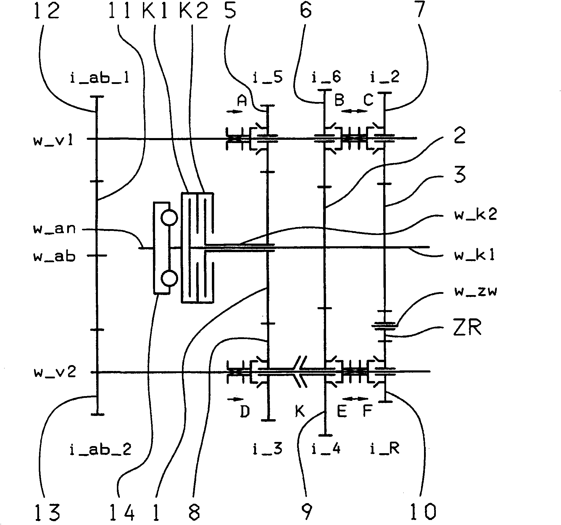
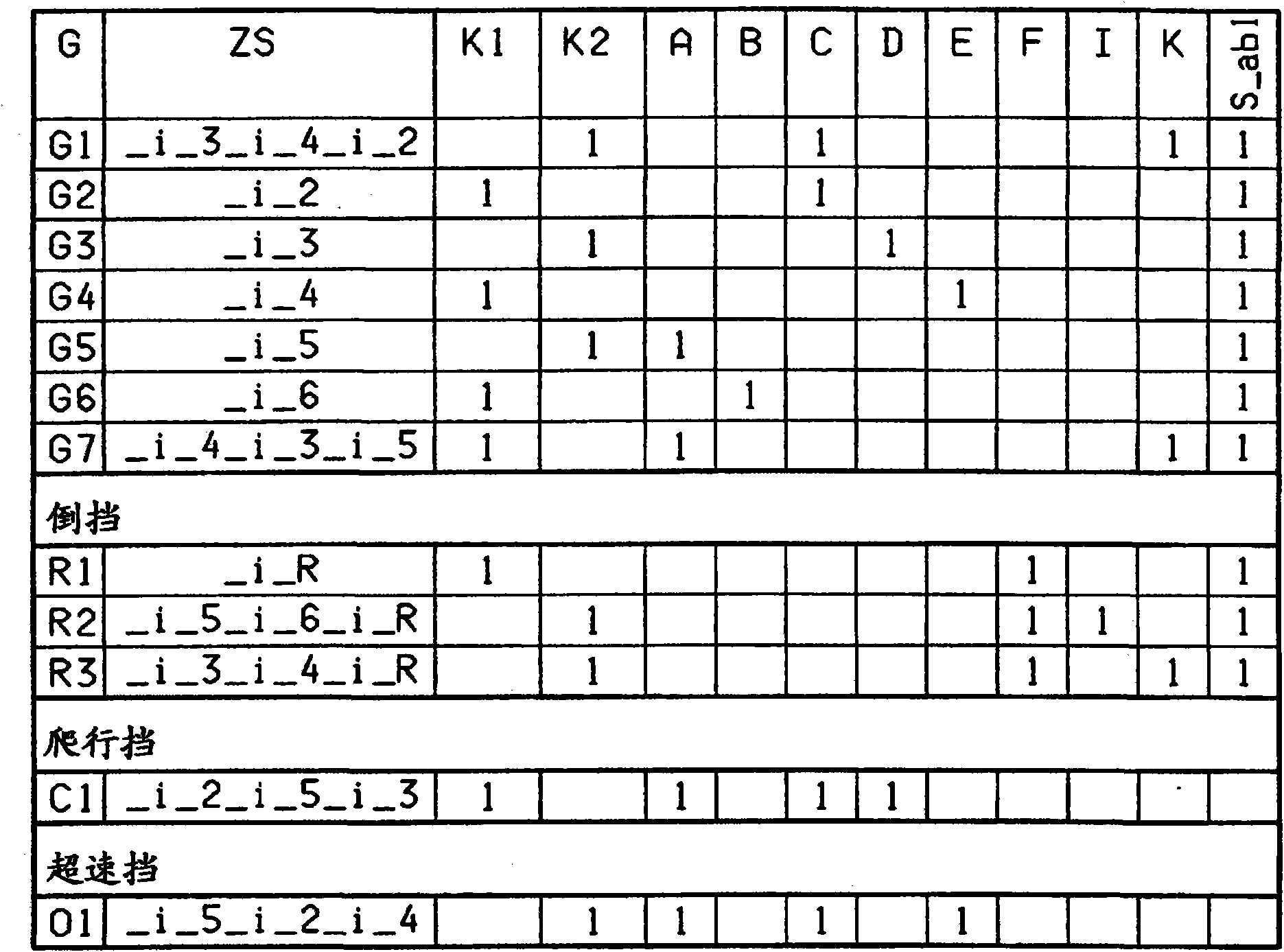
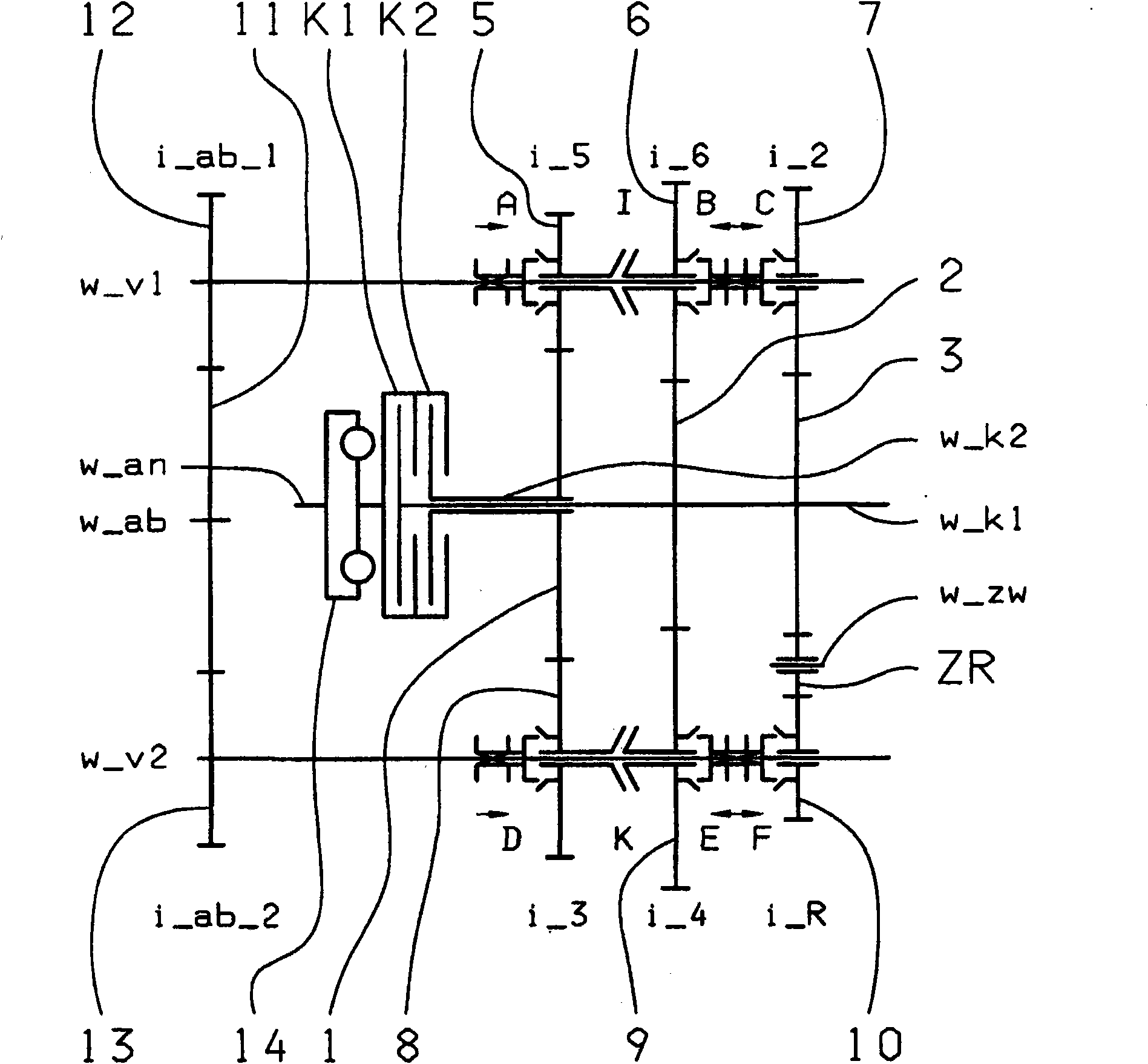
[0028] exist figure 1 with 3 A possible embodiment of a seven-speed dual clutch transmission is shown in each case. The corresponding shift diagram for the implementation is in figure 2 with 4 represented in the form of a diagram.

[0029] The seven-speed dual-clutch transmission includes two clutches K1 , K2 , whose input sides are connected to the drive shaft w_an and whose output sides are each connected to one of two transmission input shafts w_K1 , w_K2 arranged coaxially with one another. Furthermore, a torsional vibration damper 14 can be arranged on the drive shaft w_an. In addition, two countershafts w_v1 , w_v2 are provided, on which gearwheels in the form of idler gears 5 , 6 , 7 , 8 , 9 , 10 are rotatably mounted. On the two transmission input shafts w_K1 , w_K2 , gearwheels in the form of fixed gearwheels 1 , 2 , 3 , which mesh at least partially with idler gearwheels 5 , 6 , 7 , 8 , 9 , 10 , are arranged in a rotationally fixed manner. .

[0030] In order...


PUM


Abstract

The invention relates to a dual clutch transmission comprising two clutches (K1, K2), wherein three dual gear planes (5-8, 6-9, 7-10) are provided, at least one idler gear (5, 8; 6, 9; 7, 10) of the first and second countershafts (w_v1, w_v2) being associated with a fixed gear (1, 2, 3) of one of the transmission input shafts (w_K1, w_K2), and at least one idler gear (5, 6, 7, 8, 9, 10) in every dual gear plane (5-8, 6-9, 7-10) being used for at least two gears so that at least one winding path gear can be shifted via at least one shift element (K, I).

Description

technical field [0001] The invention relates to a dual clutch transmission for a vehicle of the type specified in the preamble of claim 1 . Background technique [0002] A six-speed or seven-speed dual clutch transmission is known from DE 103 05 241 A1. The dual clutch transmission comprises two clutches which are each connected with their input sides to a drive shaft and with their output sides to each of the two transmission input shafts. The two transmission input shafts are arranged coaxially with each other. The other two countershafts are arranged with axes parallel to the two transmission input shafts, and the idler gears of the two countershafts mesh with the fixed gears of the transmission input shafts. In addition, the coupling device is fastened in an axially displaceable, rotationally fixed manner on the countershaft in order to be able to engage the corresponding gearwheel. The correspondingly selected transmission ratio is transmitted to the differential via...

Claims


Application Information

Patent Timeline
Patent Type & Authority Applications(China)
IPC IPC(8): F16H3/00F16H3/093
CPCF16H2003/0931F16H2003/0826F16H2200/0091F16H2200/0026F16H3/006F16H2200/0056F16H2003/0807F16H2200/006F16H2200/0065F16H3/093Y10T74/19228Y10T74/19233
Inventor W·里格尔M·赖施M·迈尔J·瓦夫齐希R·德赖霍尔茨G·贡波尔茨贝格
Owner ZF FRIEDRICHSHAFEN AG
Why Eureka
Try Eureka