Magnetic toner

A toner and magnetic technology, applied in the field of toner, can solve the problems of fixing member contamination, low fixing performance of toner, and formation of line images too thick, and achieve stable image density, excellent low-temperature fixing performance, and suppressed image The effect of defects

Active Publication Date: 2010-08-11
CANON KK
View PDF7 Cites 0 Cited by
  • Summary
  • Abstract
  • Description
  • Claims
  • Application Information

AI Technical Summary

Problems solved by technology

[0010] However, toners having this form are known to have some problems of how they can achieve high image quality when they have a small average particle diameter of 9 μm or less
For toner whose magnetic material can hardly expose the surface of toner particles, a high charge amount can be secured, but excessive charge-up (charge-up) can be caused when images are reproduced on a large number of sheets by using a high-speed machine, particularly , when reproducing an image on a large amount of paper in a low-humidity environment, causing a drop in image density in some cases
In addition, in this toner, although a toner ensuring a high charge amount can be obtained, the toner layer on an image can become denser, so that dot reproducibility deteriorates
That is, the reduction in image quality can result in toner specks around line images, trailed images appearing, images are smeared from their trailing edges, or line images are formed too thickly
[0011] Still further, the magnetic material layer present in the toner particles can suppress bleeding of the release agent or the like from the toner particles to tend to cause problems that the toner has low fixing performance and its separability becomes low ( low releasable) causing contamination of the fixing member
However, as a result of studies on the dispersion state of individual magnetic material particles, it has been found that it cannot be said that in a region where the magnetic material exists in a high concentration formed by such non-uniformly distributed magnetic material, the dispersion state of the magnetic material is such that Satisfied

Method used


Image

  • Magnetic toner
  • Magnetic toner
  • Magnetic toner

Examples


Embodiment 1

[0242] Using Magnetic Toner 1, the following evaluations were performed. The evaluation results are shown in Table 9.

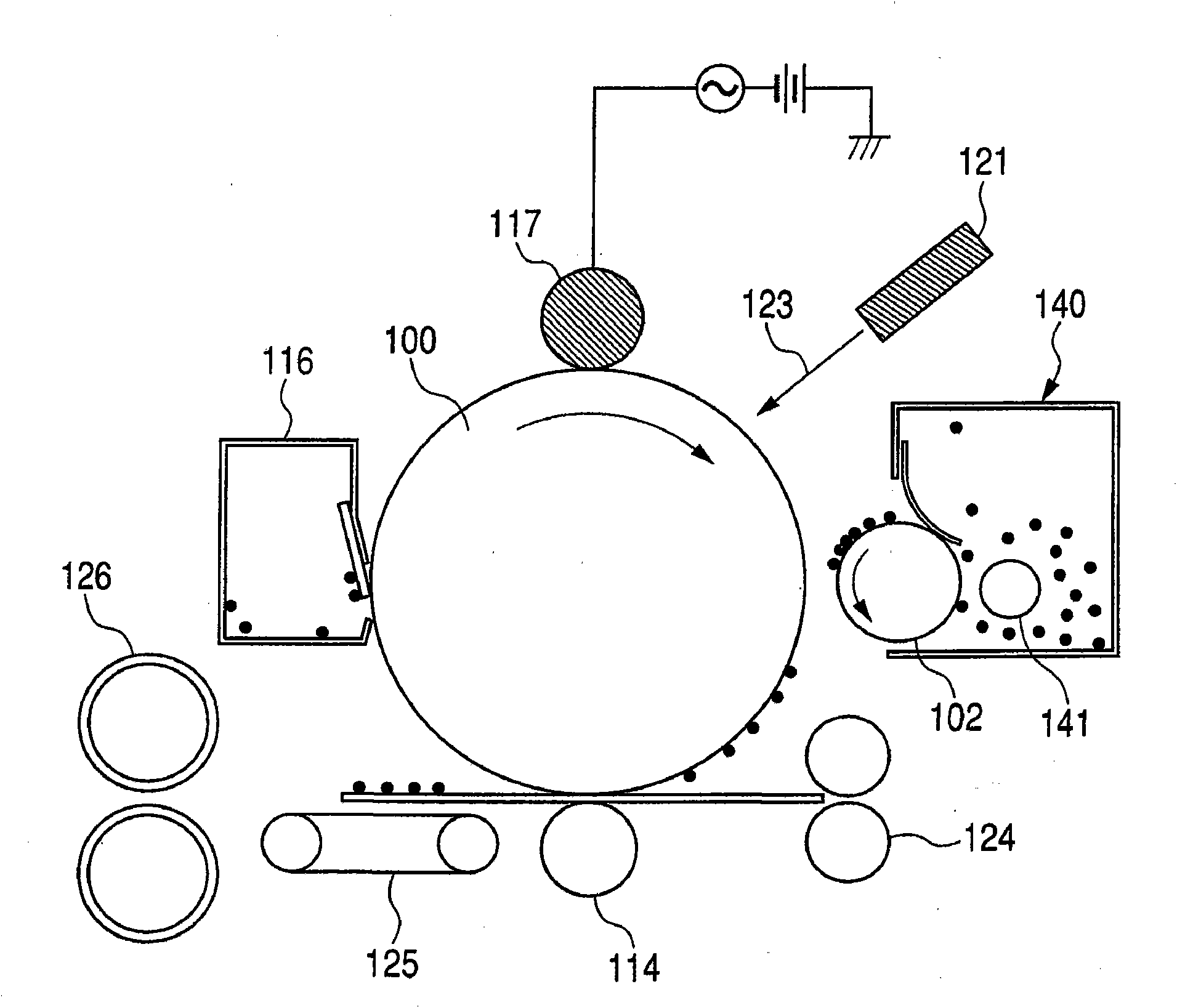
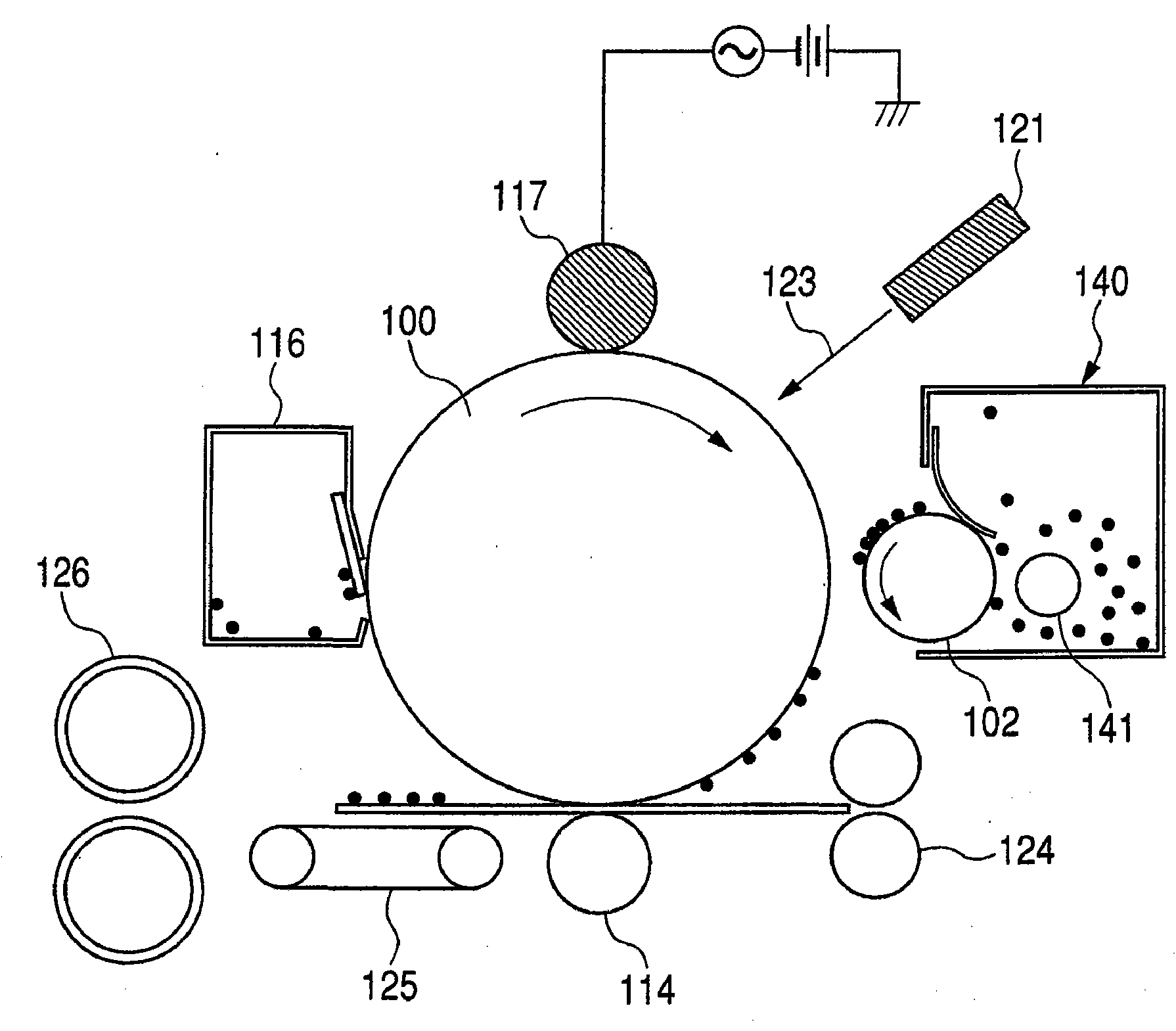
[0243] As an image forming apparatus, an LBP3000 (14 sheets / minute; manufactured by CANON INC.) modified to have a process rate of 240 mm / second was used. In a high-temperature and high-humidity environment (32.5° C. / 80% RH), a horizontal line image having a printing percentage of 3% was reproduced on 2,000 sheets in a batch mode to conduct a running test. Letter paper (75g / m2) purchased from Xerox Corporation 2 ) is used as a recording medium.

[0244] image density

[0245] After the image was reproduced on 2,000 sheets, a solid image was formed, and the density of the solid image was measured using a Macbeth densitometer (manufactured by Gretag Macbeth Ag).

[0246] A: More than 1.40.

[0247] B: 1.35 or more and less than 1.40.

[0248] C: 1.30 or more and less than 1.35.

[0249] D: Less than 1.30.

[0250] point reproducibility

[0251] After r...

Embodiment 2-9 and comparative example 2-9

[0275] Magnetic Toner 2-9 and Comparative Magnetic Toner 2-9 were similarly evaluated in the same manner as in Example 1. The results are shown in Table 9.

[0276] Table 6

[0277]

[0278] Treatment agent 1: n-C 4 h 9 Si(OCH 3 ) 3

[0279] Treatment agent 2: n-C 6 h 13 Si(OCH 3 ) 3

[0280] Treatment agent 3: n-C 8 h 17 Si(OC 2 h 5 ) 3

[0281] Treatment agent 4: n-C 10 h 21 Si(OCH 3 ) 3

[0282] Table 7

[0283]

Toner No.

magnetic material

input speed

C / E

preprocessing

crushing step

Magnetic Iron Oxide

production method

Magnetic Toner 1

5.3×10 -4

yes

Magnetic Iron Oxide 1

suspension polymerization

Magnetic Toner 2

5.3×10 -4

yes

Magnetic Iron Oxide 2

suspension polymerization

Magnetic Toner 3

2.7×10 -3

yes

Magnetic Iron Oxide 3

suspension polymerization

Magnetic Toner 4

1.6×10 -3

yes

Magnetic Iro...


PUM

PropertyMeasurementUnit
particle sizeaaaaaaaaaa
specific surface areaaaaaaaaaaa

Abstract

A magnetic toner comprising magnetic toner particles containing a binder resin and a magnetic substance as the essential components, characterized in that in a test where magnetic toner is dispersed in 5mol / l hydrochloric acid and dissolved therein, the following relationships are satisfied: 0.5 <= S3 <= 10, 40 <= S15 <= 80, 1.2 <= Sc <= 10 (wherein S3 is dissolution ratio (% by mass) of magnetic substance based on the total content of magnetic substance as determined 3 minutes after the dispersion; S15 is dissolution ratio (% by mass) of magnetic substance based on the totalcontent of magnetic substance as determined 15 minutes after the dispersion; and Sc is ratio of the amount (V3->15) of magnetic substance dissolved between 3 and 15 minutes after the dispersion to the amount (V15->30) of magnetic substance dissolved between 15 and 30 minutes after the dispersion, namely, V3->15 / V15->30) and that the dielectric loss tangent (tan delta)of the toner at 25 DEG C and a frequency of 1.0104Hz is 2.0x10⁻³ to 1.5x10⁻².

Description

technical field [0001] The present invention relates to a toner used in a recording method using electrophotography, electrostatic recording, electrostatic printing or toner jet recording. Background technique [0002] Various methods are conventionally known as electrophotography. Generally, a copy or a print is obtained by forming an electrostatic latent image in various ways by using a photoconductive material on an electrostatically charged image bearing member (hereinafter also referred to as a "photosensitive member"), and then by using a toner. The latent image is developed with a toner to form a toner image as a visible image, and further, if necessary, the toner image is transferred to a recording medium such as paper, and then the toner image is fixed on the recording medium by heat and / or pressure. on the medium. Devices used for this image formation include copiers, printers, and the like. [0003] Convert these printers or copiers from analog to digital and m...

Claims


Application Information

Patent Timeline
Patent Type & Authority Applications(China)
IPC IPC(8): G03G9/083G03G9/087
CPCG03G9/0839G03G9/0833G03G9/0835G03G9/08711G03G9/0838G03G9/0827
Inventor 广子就一道上正马笼道久柳濑惠理子松井崇佐野智久榊原彰铃村祯崇
Owner CANON KK
Why Eureka
Try Eureka