Method and system for transmitting and receiving signals

A signal and receiver technology, applied in the field of sending and receiving signals and systems, to solve problems such as difficult signal decoding

Active Publication Date: 2010-08-11
LG ELECTRONICS INC
View PDF0 Cites 12 Cited by
  • Summary
  • Abstract
  • Description
  • Claims
  • Application Information

AI Technical Summary

Problems solved by technology

Therefore, if P2 is able to provide information on any data symbol immediat

Method used


Image

  • Method and system for transmitting and receiving signals
  • Method and system for transmitting and receiving signals
  • Method and system for transmitting and receiving signals

Examples


Embodiment approach

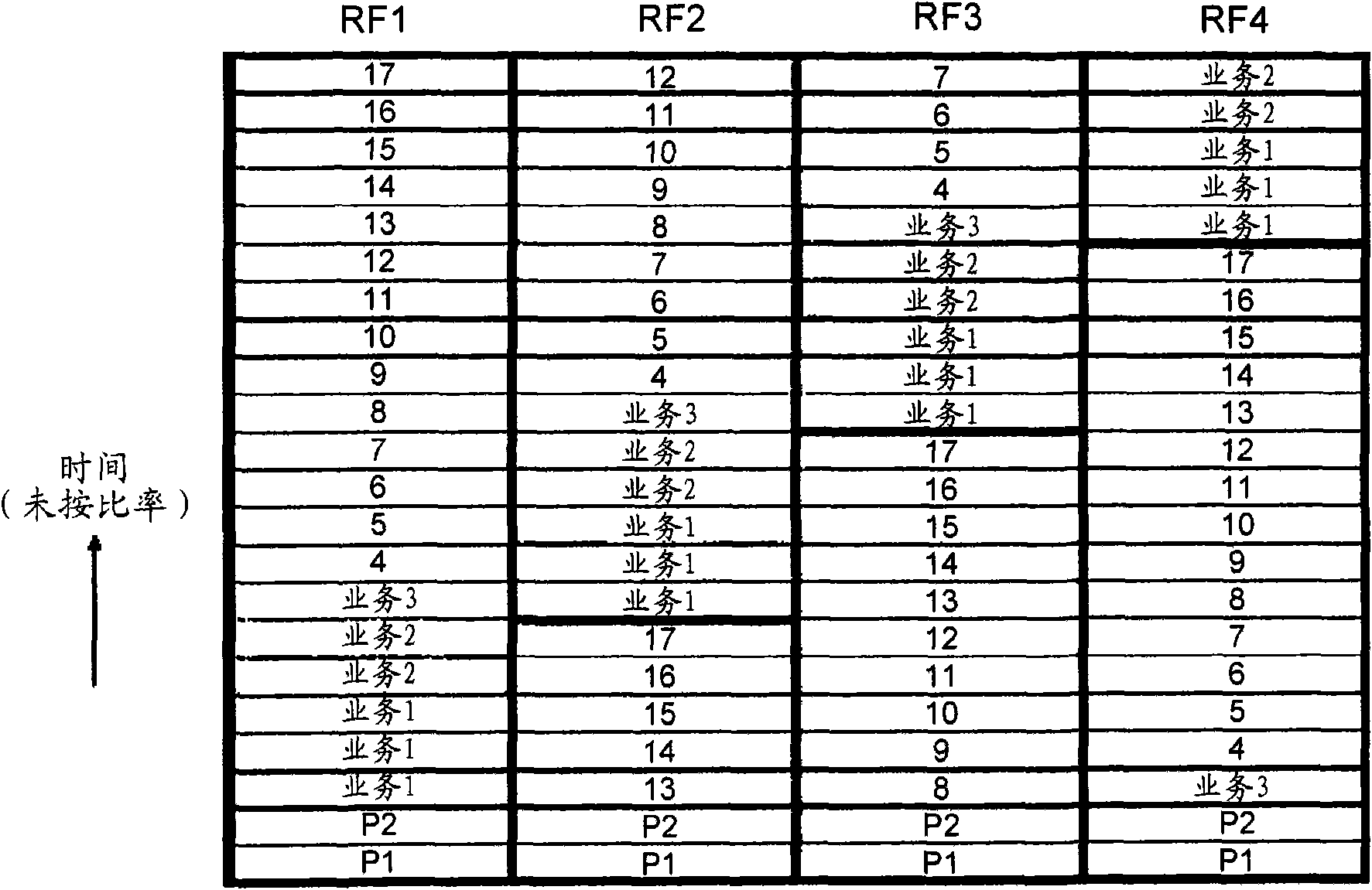
[0070] According to yet another embodiment, by numbering the data symbols, a method of easily locating traffic and pilot locations can be provided.

[0071] According to yet another embodiment, the calculation time and amount of calculation required by the receiver to detect and recover the signal can be greatly reduced. In particular, the time required to recover the transmitted signal results in a limitation of the number of time slots that traffic can occupy. Can provide a way to change the size of the business.

[0072] Furthermore, the receiver according to one of the embodiments performs faster and at a lower cost than receivers according to the prior art.

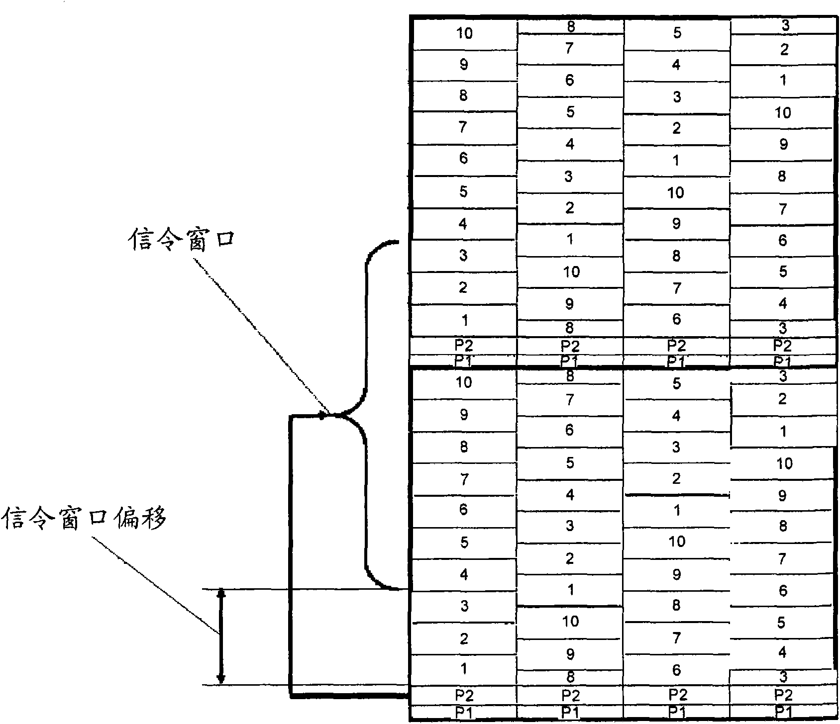
[0073] According to yet another embodiment, by providing a method of efficiently transmitting P1 and P2 symbols, a method of reducing physical load and latency at the receiver may be provided.

[0074] Finally, through novel signaling, a method for automatically identifying newly added TFS ensembles at the receiver...


PUM


Abstract

The present invention relates to an efficient receiver, and methods of efficiently receiving the signals. In particular, the present invention relates to a method of efficiently receiving a first pilot symbol and a second pilot symbol to reduce physical load and latency in a receiver. In addition, the present invention relates to a method of inserting the first pilot symbol and the second pilot symbol in RF channels.

Description

technical field [0001] This application claims priority to US Provisional Patent Application 60 / 973,420, filed September 18, 2007, which is hereby incorporated by reference in its entirety. [0002] The present invention relates to a method for effectively sending and receiving signals of an OFDM (Orthogonal Frequency Division Multiplexing) system including TFS (time-frequency slicing, time-frequency slicing) and a high-efficiency transmitter and receiver. Background technique [0003] TFS (time-frequency slicing, time-frequency slicing) has been introduced in the next generation broadcast network. Such as figure 1 As shown, a broadcast service can be sent in multiple time-RF channel domains. figure 1 Shown is the statistical multiplexing gain that enables more traffic to be sent efficiently by spatially expanding from the previous single RF channel band to multiple RF channel bands in the multiplexing step at the transmitter. In addition, frequency diversity gains can be...

Claims


Application Information

Patent Timeline
IPC IPC(8): H04L27/26
CPCH04L27/2655H04L5/0096H04L5/0092H04L27/2675H04L2025/03414H04L5/0048
Inventor 高祐奭文相喆
Owner LG ELECTRONICS INC
Why Eureka
Try Eureka