Sintering stage of slope sintering machine

A technology of sintering machine and sintering section, which is applied in the direction of furnace type, furnace, lighting and heating equipment, etc. It can solve the problem that the technical indicators and energy consumption indicators cannot meet the requirements, limit the speed increase of flat sintering machines and the expansion of area, and the production line turns Time-stopping and other problems, to achieve good energy-saving effect, low load, and short installation period

Inactive Publication Date: 2010-08-18
张健
View PDF5 Cites 4 Cited by
  • Summary
  • Abstract
  • Description
  • Claims
  • Application Information

AI Technical Summary

Problems solved by technology

However, the operating cost is very high, which is mainly reflected in the fact that continuous production is not possible, the production line stops when it turns, and the transfer method of the trolley at the head and tail of the machine is a single vehicle-type back-and-forth walking method, which takes a long time and limits the flat burning machine. The acceleration and the expansion of the area
There is a lot of air leakage between the trolleys of the sintering machine body, and the technical indicators and energy consumption indicators are not up to the requirements

Method used


Image

  • Sintering stage of slope sintering machine
  • Sintering stage of slope sintering machine
  • Sintering stage of slope sintering machine

Examples


Embodiment Construction

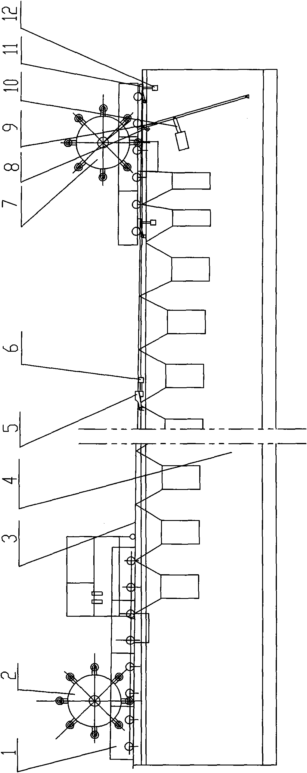
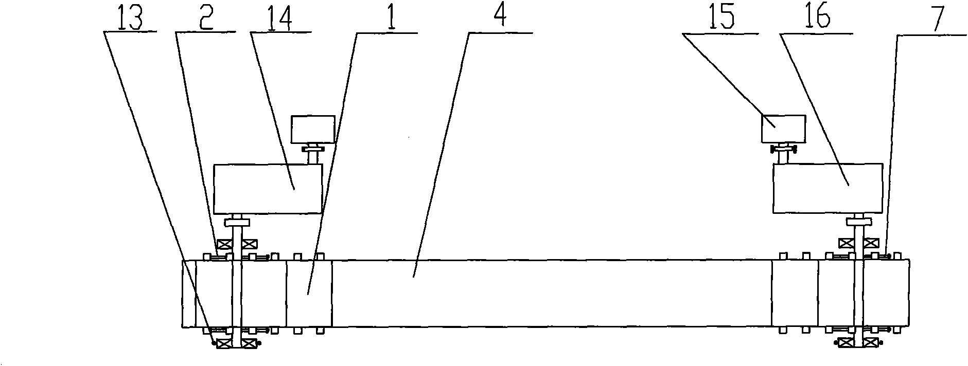
[0026] The specific implementation manner of the present invention will be further described below in conjunction with the examples given in the accompanying drawings.

[0027] Such as figure 1 , figure 2 As shown, the sintering section of a slope sintering machine of the present invention includes a sintering machine body 4, a driving mechanism 2, a trolley track 3, a bottoming hopper, a mixing hopper, a head sealing device, an igniter, a hot air sintering section, a bellows, The tail sealing device and the trolley 1 are characterized in that the trolley track 3 is arranged with a high feed end and a low ore discharge end, and a damping mechanism 7 is provided at the tail of the sintering machine body 4. A fine-tuning mechanism 13 is provided on the bearing seat of the driven end of the transmission shaft of the driving mechanism 2 and the damping mechanism 7, and a fast-moving mechanism is provided at the tail of the sintering machine body 4, and a fast-moving mechanism is...


PUM

PropertyMeasurementUnit
angleaaaaaaaaaa

Abstract

The invention relates to the technical field of sintering equipment, in particular to a sintering stage of a slope sintering machine. The sintering stage is characterized in that a trolley track is inclined with a higher feed end and a lower ore removal end, a damping mechanism is arranged on the tail of the machine body of the sintering machine, two fine-adjustment mechanisms are separately arranged on the bearing seats of the driven ends of the transmission shafts of a driving mechanism and the damping mechanism, a fast feeding mechanism is arranged on the tail of the machine body of the sintering machine, two trolley spacing mechanisms are separately arranged on the tail of the trolley track and between the head and the tail of the trolley track, and the driving wheel of the driving mechanism and the damping wheel of the damping mechanism are both next to and connected with the shaft sleeve which is arranged on the axle of the trolley and near the wheels of the trolley; and the fast feeding hydraulic cylinder of the fast feeding mechanism and the spacing hydraulic cylinders of the trolley spacing mechanisms are connected with an automatic control system. The invention has good energy-saving effect and low air leakage ratio of equipment, and the enlargement of equipment is easy to realize by using the invention.

Description

technical field [0001] The invention belongs to the technical field of sintering equipment in the smelting industry, in particular to a sintering section of an inclined plane sintering machine. Background technique [0002] When carrying out sintering production in the smelting industry, it is necessary to configure the main equipment of the sintering machine. Belt-type sintering machines, ring-type sintering machines, and stepping-type plane sintering machines are popular now. Belt-type sintering machines have low production costs, good technical indicators, and can carry out large-scale production, but the initial construction costs are large and the construction period Long, high maintenance costs. The ring type sintering machine has large investment, high production cost, poor indicators, and cannot carry out large-scale production, so it has been gradually eliminated. The step-by-step planar sintering machine has a short construction period, less investment and quick ...

Claims


Application Information

Patent Timeline
Patent Type & Authority Applications(China)
IPC IPC(8): F27B21/08
Inventor 张健
Owner 张健
Why Eureka
Try Eureka