
Stock bin control system

A control system and silo technology, applied in the direction of electrical program control, sequence/logic controller program control, etc., can solve the problems that the detection probe is easily covered, the material level detection is distorted, and the interface of the material forms a pile angle, etc. Achieve the effect of solving easy damage failure and measurement result distortion

Inactive Publication Date: 2010-08-18
SINOSTEEL ANSHAN RES INST OF THERMO ENERGY CO LTD
View PDF6 Cites 18 Cited by
  • Summary
  • Abstract
  • Description
  • Claims
  • Application Information

AI Technical Summary

Problems solved by technology

These two measurement methods have some disadvantages, such as: contact level gauge, the detection element should be in contact with the material, and it is easy to be damaged in the case of strong impact
[0004] The non-contact level gauge determines the level of the material through the reflection of the radiation emitted by the probe of the detection element when it encounters the material. However, in the case of strong dust and strong adhesion, the detection probe is easily covered, so that it cannot be detected. material position, and when the material inlet is on one side of the silo, the interface of the material will form a pile angle, resulting in distortion of the material level detection
[0005] 2. For the silo where the material medium for storage is block or powder, in order to control the discharge speed, the discharge port is often made into a straight section. When the silo is discharging, the discharge port is easy to block. Once The occurrence of material blockage will seriously affect production and bring great trouble to maintenance
There is almost no detection method for the unloading clogging phenomenon

Method used


Image

  • Stock bin control system
  • Stock bin control system
  • Stock bin control system

Examples


Embodiment Construction

[0021] The specific embodiment of the present invention will be further described below in conjunction with accompanying drawing:

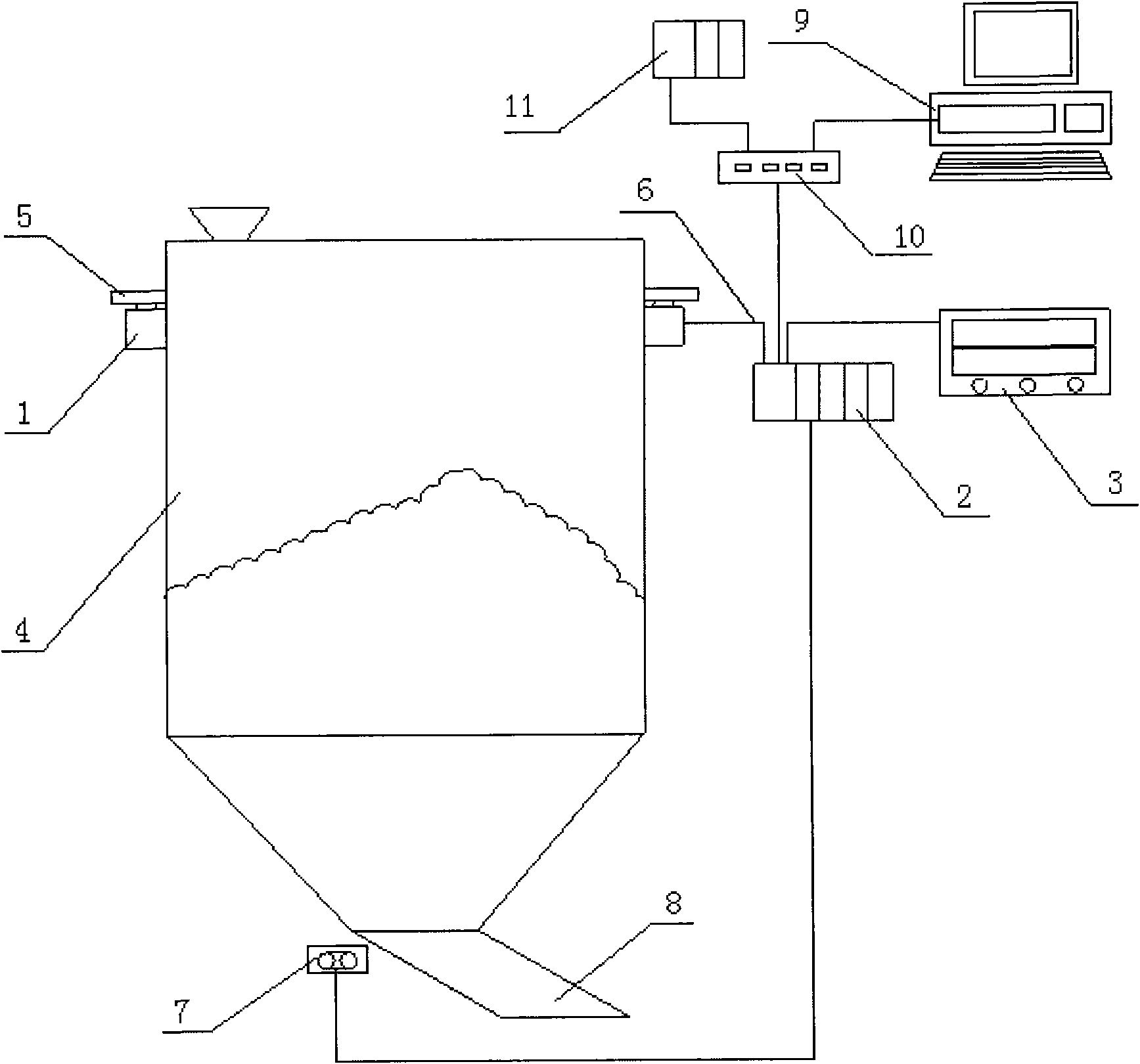
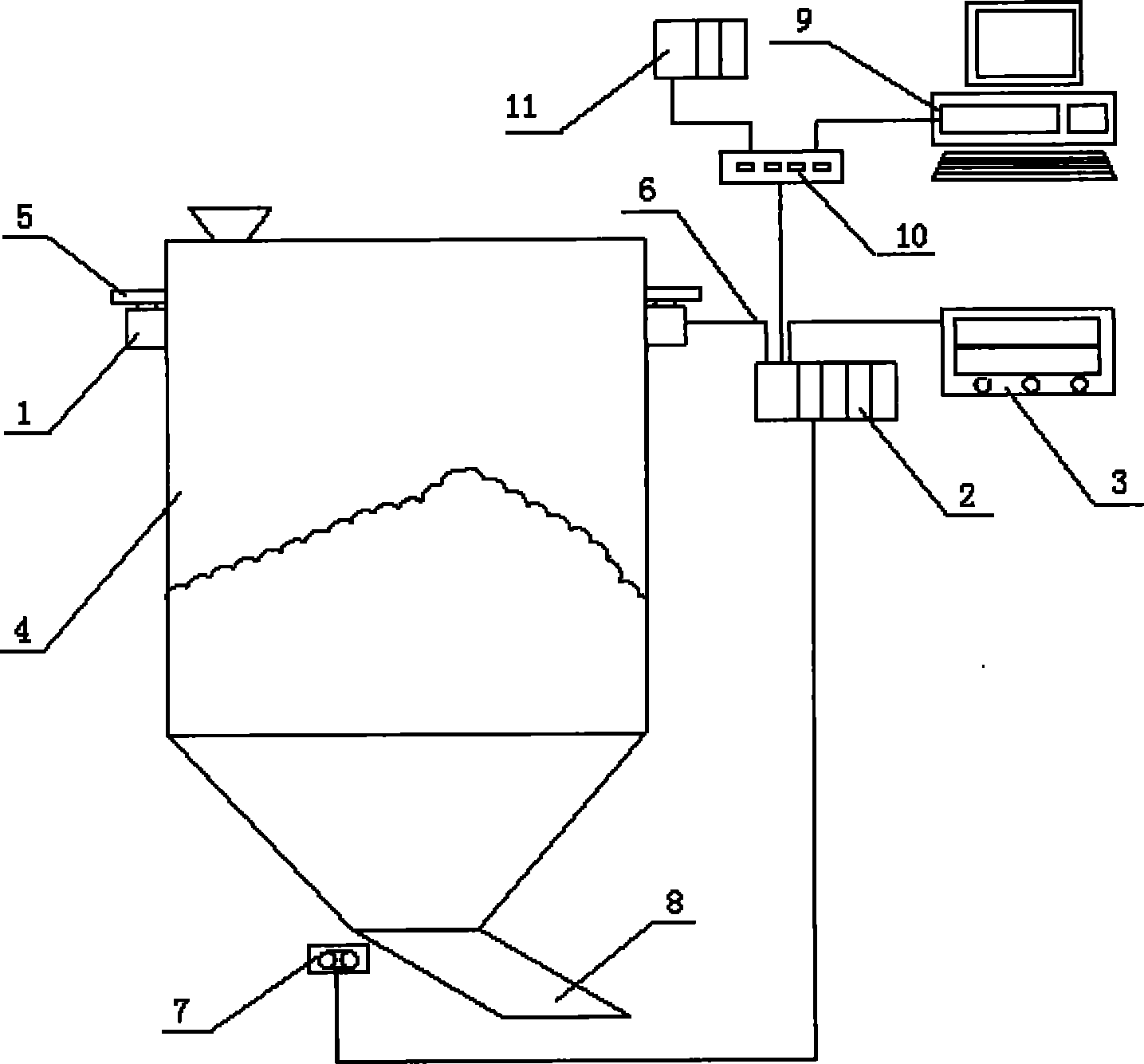
[0022] See figure 1 , a silo control system, comprising a load cell 1, a programmable controller 2, and a display instrument 3, the load cell 1 is arranged under the support 5 of the silo 4, and the unloading mechanism 7 is arranged at the discharge port 8 of the silo In order to prevent electromagnetic interference, the programmable controller 2 is respectively connected to the load cell 1 and the display instrument 3 through a two-core shielded cable 6. The standard 4~ 20mA signal transmission, the input and output of all signals are relative to the programmable controller 2, that is, the load cell 1 transmits the input signal to the programmable controller 3, and the programmable controller 2 sends the display instrument 3 as an output signal. Load cell 1 generally has 3 to 4 points. The programmable controller 2 is equipped with a communicat...


PUM


Abstract

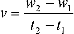
The invention relates to a stock bin control system, which comprises a weighting sensor, a programmable controller and a display instrument. The weighting sensor is arranged under a supporting seat of the stock bin, the programmable controller is respectively connected with the weighting sensor and the display instrument through a shielded cable, and a standard 4-20mA signal transmission is adopted for the weighting sensor, the programmable controller and the display instrument. The weighting sensor is generally set with 3-4 points. The stock bin control system is characterized by indirectly measuring the material level of the material stock in the stock bin by means of weighing, and calculating the material flow rate through the weight change to accurately determine the condition of the material discharge and jamming. The invention has the advantages that: the method of weighing is adopted to directly measure the material level of the material stock in the stock bin and the material flow rate is calculated through the weight change to accurately determine the condition of the material discharge and jamming, thereby solving the problems of easy damage and failure of the contact charge level indicator and the non-contact charge level indicator and the infidelity of the measured result, and particularly solving the problem of detection of jamming in the discharge port.

Description

technical field [0001] The invention relates to a control system for measuring the material level of a silo and detecting a discharge blockage. Background technique [0002] At present, the structural forms of the silo mainly include open type and closed type, and the state of the material in the silo can be solid, liquid, and gas. [0003] 1. For different material medium characteristics, there are usually two measurement methods for the detection of material level: contact type and non-contact type. These two measurement methods have some disadvantages, such as: contact level gauge, the detection element should be in contact with the material, and it is easy to be damaged in the case of strong impact. [0004] The non-contact level gauge determines the level of the material through the reflection of the radiation emitted by the probe of the detection element when it encounters the material. However, in the case of strong dust and strong adhesion, the detection probe is ea...

Claims


Application Information

Patent Timeline
IPC IPC(8): G05B19/05
Inventor 王卫红李佳峰李晓峰
Owner SINOSTEEL ANSHAN RES INST OF THERMO ENERGY CO LTD
Learn More