Automatic identification system for surgical cutter

A surgical operation and self-identification technology, which is applied in the field of self-identification system, can solve the problems of increasing the work intensity of doctors, prolonging the operation time, and increasing the risk of surgery, so as to avoid the operation risk and shorten the operation time.

Active Publication Date: 2010-08-18
CHONGQING XISHAN SCI & TECH
View PDF0 Cites 14 Cited by
  • Summary
  • Abstract
  • Description
  • Claims
  • Application Information

AI Technical Summary

Problems solved by technology

[0004] The obvious disadvantage of the prior art is: but because there are too many types of external knives, if the knife identification module is not added, the doctor needs to manually set the knife parameters when performing surgical operations to replace the knives, thereby prolonging the operation time and increasing the number of doctors. Intensity of work, at the same time, when setting parameters, the risk of surgery may be increased due to incorrect parameter settings

Method used


Image

  • Automatic identification system for surgical cutter
  • Automatic identification system for surgical cutter
  • Automatic identification system for surgical cutter

Examples


Embodiment 1

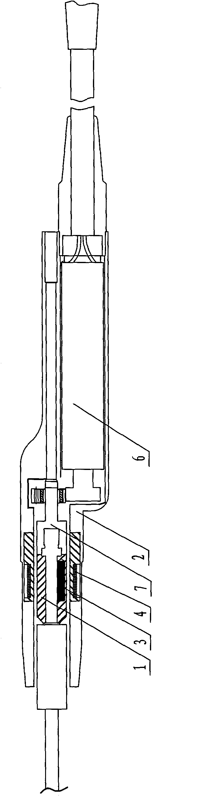
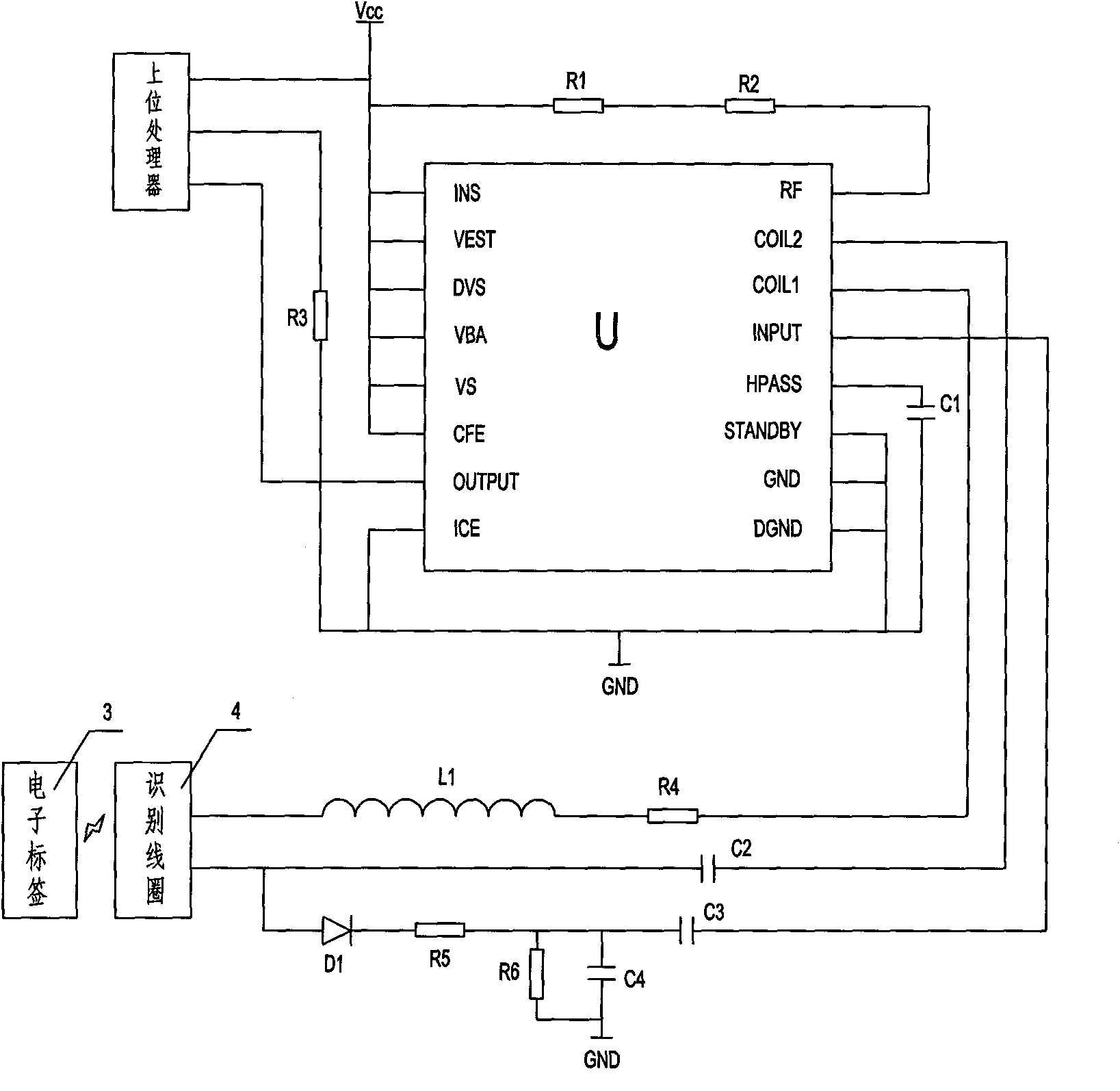
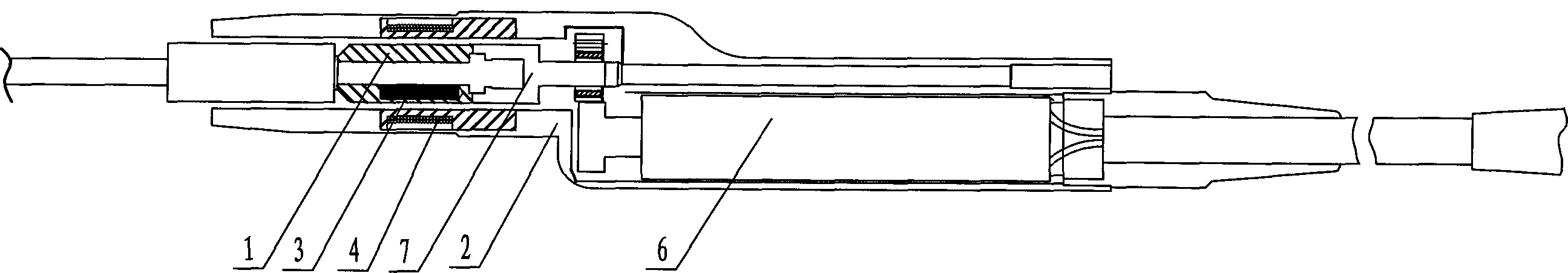
[0033] Such as figure 1 Shown: a self-identification system for surgical knives, including an external knife and a controller, wherein the external knife is provided with a plug 1, the controller is provided with a socket 2 and a processing circuit, and the external knife and the controller are connected through the plug 1, The socket 2 is assembled and connected, and the key is that an electronic tag 3 is installed on the plug 1, an identification coil 4 is installed on the socket 2, the identification coil 4 is connected to the processing circuit, and the identification coil 4 obtains the electronic tag 3 After receiving the electromagnetic information, a signal is sent to the processing circuit, the output end of the processing circuit is connected to the input end of the control motor 6, and the output shaft of the control motor 6 is connected to the external tool.

[0034] Each type of external tool is respectively configured with a corresponding radio frequency signal in...

Embodiment 2

[0058] Embodiment 2 The plug 1 and the socket 2, the electronic tag 3 and the identification coil 4 are installed at the junction of the control motor 6 and the transmission cable.

Embodiment 3

[0059] Embodiment 3 The plug 1 and the socket 2, the electronic label 3 and the identification coil 4 are installed on the casing of the controller, that is, the junction of the controller and the transmission cable.

[0060] Its specific structure is as follows:

[0061] Example 2:

[0062] The handle end of the external tool is connected to the output shaft of the control motor 6;

[0063] The control motor 6 is fixedly connected to the plug 1, the plug 1 is a non-metallic plug 1, and a radio frequency card installation hole is also arranged in the plug 1, and the electronic tag 3 is fixed in the radio frequency card installation hole;

[0064] There is a circle of coil installation holes in the socket wall of the socket 2, and the identification coil 4 is set in the coil installation holes. When the plug 1 is inserted into the socket 2, the radio frequency card extends into the identification coil 4.

[0065] Example 3:

[0066] The socket 2 is fixed on the shell of the...


PUM


Abstract

The invention discloses an automatic identification system for a surgical cutter, which comprises an external cutter and a controller. The external cutter is provided with a plug; and the controller is provided with a socket and a processing circuit. The system is characterized in that: the plug is provided with an electronic tag; the socket is provided with an identification coil; the identification coil is connected with the processing circuit; the identification coil acquires electromagnetic information of the electronic tag, and then sends a signal to the processing circuit; and the output end of the processing circuit is connected with the input end of a control motor. The system has the advantages that: the system can automatically identify the type of the cutter currently connected with the controller, and can automatically replace drivers of the corresponding cutters according to the type of the cutter; a doctor can set working parameters before a surgery, and directly assembles the cutter during the surgery to directly perform the surgery so as to shorten surgical time and avoid surgical risk caused by parameter setting errors.

Description

technical field [0001] The present invention is mainly used in the technical field of surgery, and specifically is a self-identification system for surgical knives. Background technique [0002] Many minimally invasive surgical operations require electric knives to be implemented. Surgical electric knives are mainly provided with external knives and controllers, wherein the external knives are provided with plugs, and the controller is provided with sockets and processing circuits. The plug and the socket are assembled and connected, the output end of the processing circuit is connected with the input end of the control motor, and the output shaft of the control motor is connected with the external tool. For different surgical operations, the corresponding external cutters are replaced by plugs and sockets. Such as ENT surgery, its power tool is mainly used for planing soft tissue or grinding bone tissue in ENT surgery. There are dozens of types such as single-sided intern...

Claims


Application Information

Patent Timeline
Patent Type & Authority Applications(China)
IPC IPC(8): G06K7/10A61B17/00
Inventor 郭毅军
Owner CHONGQING XISHAN SCI & TECH
Why Eureka
Try Eureka