LED lighting driving circuit and method by using compatible silicon controlled light adjuster to adjust light

A technology of LED lighting and driving circuit, which is applied in the direction of lighting devices, electric lamp circuit layout, light source, etc., and can solve problems such as inability to adjust light, unstable control signal, and inability to correctly sample dimming signals

Active Publication Date: 2010-08-18
SHANGHAI BRIGHT POWER SEMICONDUCTOR CO LTD
View PDF6 Cites 14 Cited by
  • Summary
  • Abstract
  • Description
  • Claims
  • Application Information

AI Technical Summary

Problems solved by technology

But in fact, due to the presence of leakage current in the thyristor dimming circuit, this will cause the control signal to be unstable, so that the dimming signal cannot be sampled correctly and the dimming cannot be performed. In severe cases, it will cause abnormal phenomena such as flickering of the LED.

Method used


Image

  • LED lighting driving circuit and method by using compatible silicon controlled light adjuster to adjust light
  • LED lighting driving circuit and method by using compatible silicon controlled light adjuster to adjust light
  • LED lighting driving circuit and method by using compatible silicon controlled light adjuster to adjust light

Examples


Embodiment Construction

[0024] Specific embodiments of the present invention will be described in detail below in conjunction with the accompanying drawings.

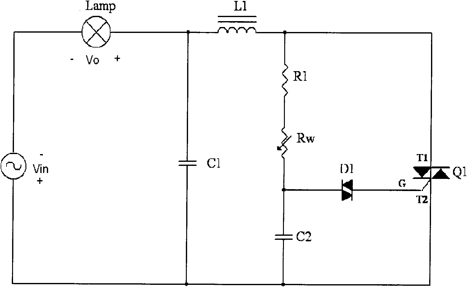
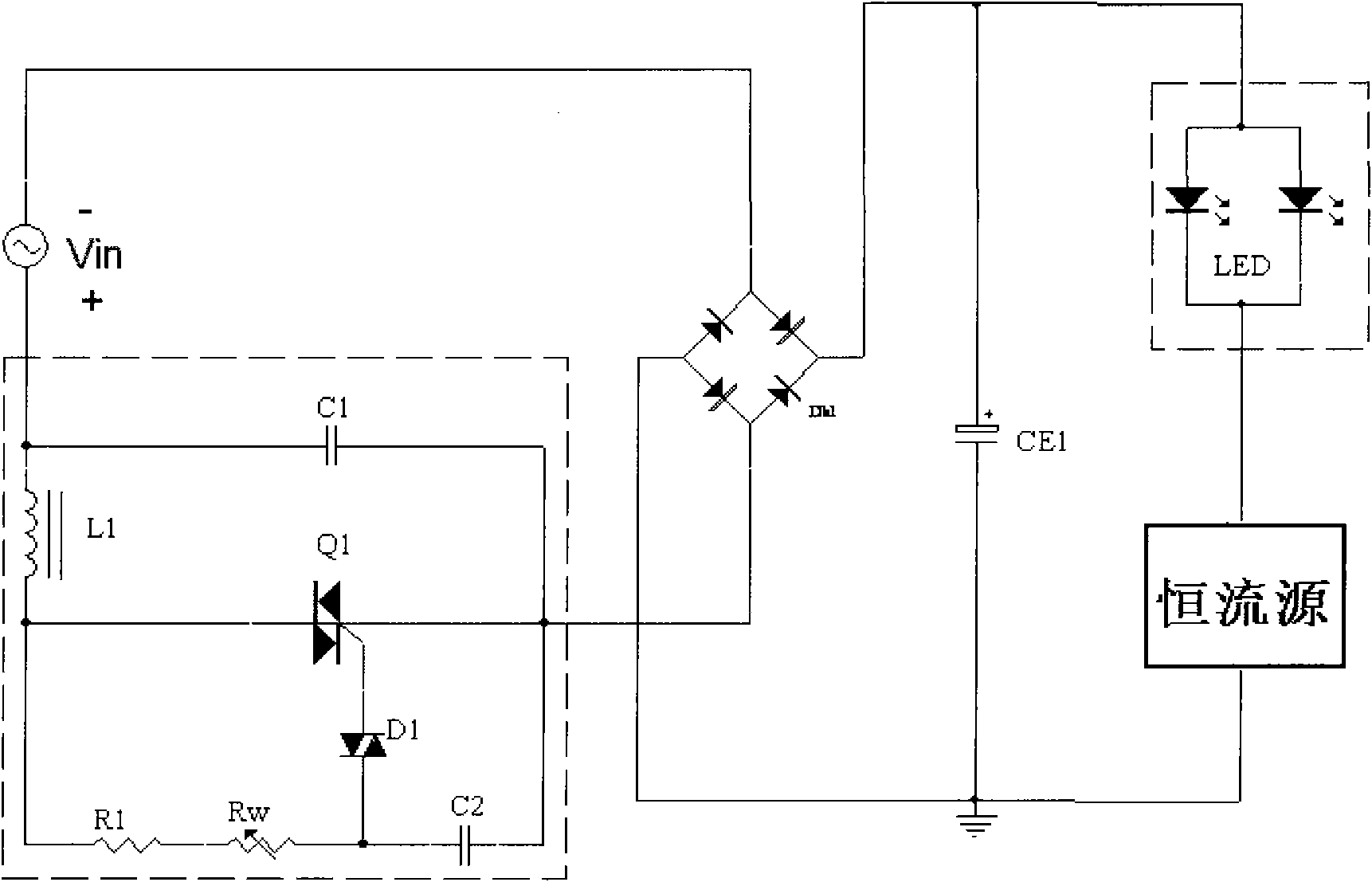
[0025] Such as Figure 4 and 5 As shown, an LED thyristor dimming circuit of the present invention is an input signal connected in series with a thyristor dimming circuit 1 and a rectifier bridge circuit 2, and the positive output of the rectifier bridge circuit 2 is connected to a signal sampling and filtering The circuit 3, the signal sampling and filtering circuit 3 is connected in series with a voltage-controlled current source 4 and a load LED5; the rectifier bridge circuit 2 is also connected in series with the leakage absorption circuit 6. The signal sampling and filtering circuit is as follows: the positive phase input terminal of a comparator U1 is connected to the positive terminal of a comparison reference voltage Vr, the negative terminal of the comparison reference voltage Vr is grounded, and the output terminal of the comparator...


PUM


Abstract

The invention discloses an LED lighting driving circuit and a method by using a compatible silicon controlled light adjuster to adjust light, an input signal is connected with a silicon controlled light adjusting circuit and a rectifier bridge circuit in series, an output anode of the rectifier bridge circuit is connected with a signal sampling and filtering circuit which is connected with a voltage controlled current source and a loaded LED in series; the output anode of the rectifier bridge circuit is connected with an electric leakage protection circuit; the signal sampling and filtering circuit is characterized in that a normal phase input end of a comparator is connected with the positive end of a benchmark voltage, the negative end of the benchmark voltage is connected to the ground, an output end of the comparator is connected an input end of a phase inverter, the output end of the phase inverter is connected with the input end of a low-pass filter, and the output end of the low-pass filter is connected with a control terminal of the voltage-controlled current source. The LED lighting driving circuit by using the compatible controlled silicon light adjuster to adjust light adopts a silicon controlled electric leakage absorbing circuit to enable the sampled silicon controlled light adjusting signal to be accurate and stable, and the light adjusting effect of the loaded LED is good.

Description

technical field [0001] The invention relates to a dimmable LED driving circuit, in particular to an LED lighting driving circuit compatible with the dimming of a thyristor dimmer and a control method. Background technique [0002] Since the traditional thyristor dimming circuit was originally designed for 40~600W incandescent lamps, and the equivalent model of incandescent lamps is a pure resistance. Therefore, when such a thyristor dimming circuit is directly used in a 3~20W LED drive circuit, the dimmer will work in an abnormal state. [0003] figure 1 It is a schematic diagram of a traditional thyristor dimming circuit. L in the figure is an incandescent lamp. L1 and C1 are filter circuits (mainly absorbing surge voltage and current during circuit switching). Q1 is a bidirectional thyristor. R1, Rw, C2, and D1 form a silicon controlled rectifier opening control circuit. Among them, Rw is an adjustable potentiometer. By changing the resistance value of Rw, the turn-o...

Claims


Application Information

Patent Timeline
Patent Type & Authority Applications(China)
IPC IPC(8): H05B37/02
Inventor 张义胡黎强赵新江
Owner SHANGHAI BRIGHT POWER SEMICONDUCTOR CO LTD
Why Eureka
Try Eureka