Classification device, standing pulverizer using the classification device, and coal burning boiler apparatus

A classification device, vertical technology, applied in solid separation, chemical instruments and methods, separation of solids from solids by air flow, etc. And other issues

Active Publication Date: 2010-08-18
MITSUBISHI POWER LTD
View PDF1 Cites 1 Cited by
  • Summary
  • Abstract
  • Description
  • Claims
  • Application Information

AI Technical Summary

Problems solved by technology

Therefore, fine powder is bitten into the press roller, which causes the self-excited vibration of the roller, and the amount of coal held in the pulverizing part of the pulverizer increases, resulting in a reduction in the pulverization amount and an increase in the pulverization power.

Method used


Image

  • Classification device, standing pulverizer using the classification device, and coal burning boiler apparatus
  • Classification device, standing pulverizer using the classification device, and coal burning boiler apparatus
  • Classification device, standing pulverizer using the classification device, and coal burning boiler apparatus

Examples


Embodiment Construction

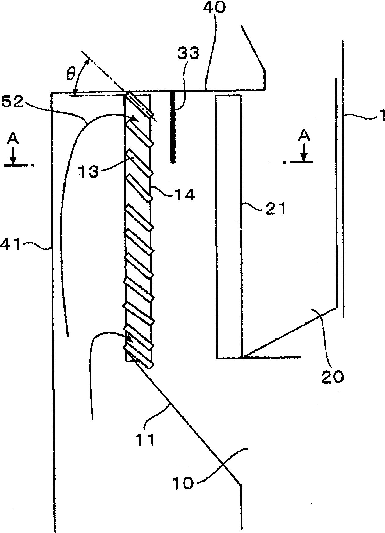
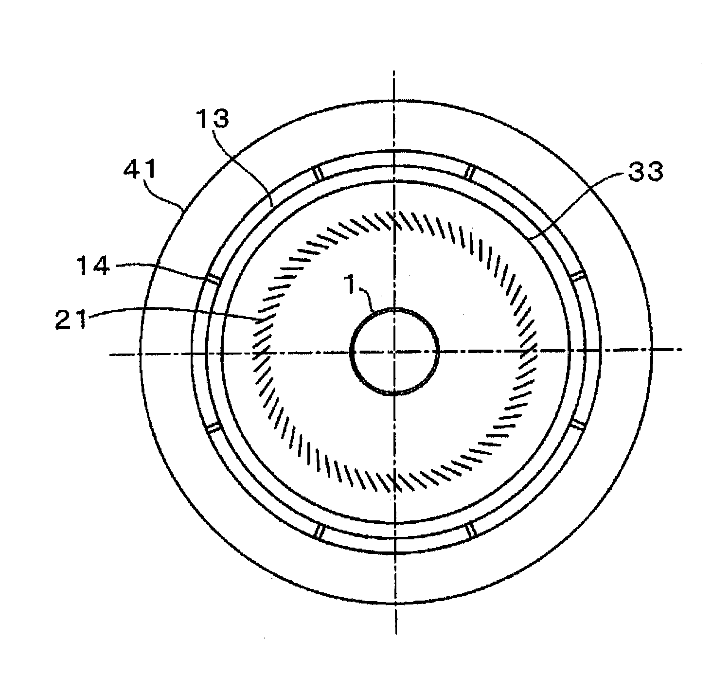
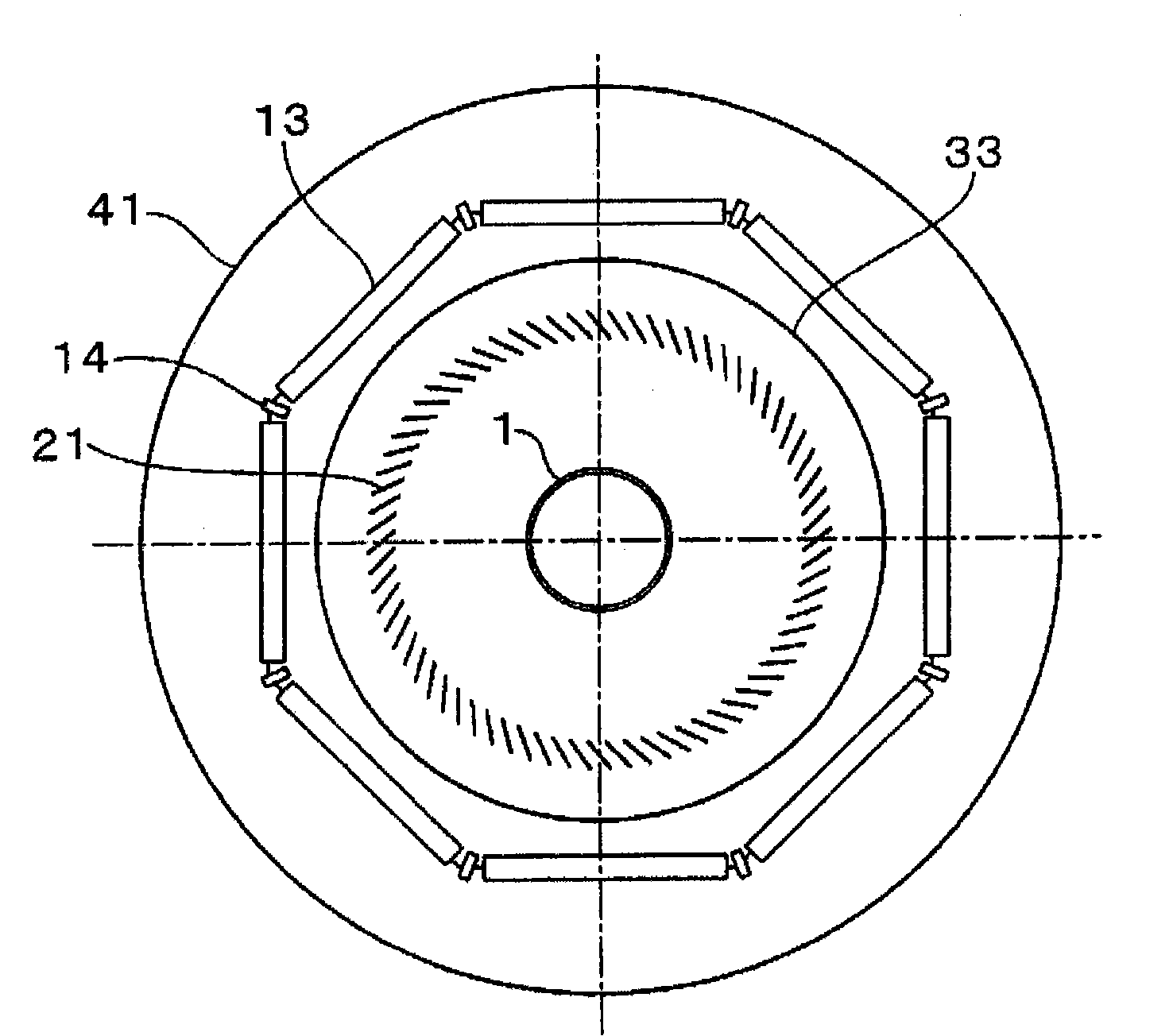
[0042] Next, embodiments of the present invention will be described with reference to the drawings. Figure 1 to Figure 3 is a diagram for explaining the classifying device according to the first embodiment of the present invention, figure 1 It is a schematic longitudinal sectional view showing the main part of the classification device, figure 2 yes figure 1 A schematic cross-sectional view on line A-A of image 3 Indicates a modified example of a fixed fin figure 1 A schematic cross-sectional view on line A-A of . In addition, the schematic structure and Figure 27 The devices shown are the same, so their description is omitted.

[0043] Such as figure 1 As shown, the classifier is a two-stage classifier in which a substantially cylindrical stationary classifier 10 disposed on the inlet side of the classifier and a rotary classifier 20 disposed therein are combined.

[0044] Stationary classifier 10 comprises: long plate-shaped supporting part 14; figure 2 The f...


PUM


Abstract

To provide a classification device which can provide a fine powder product into which coarse particles have not been significantly included. A classification device characterized by comprising a combination of an installation pitch P and a width L in a fixed fin (13) satisfying the following formula: P / L = 0.042 (theta - 50) + 0.64 to 0.019 (theta - 50) + 0.22 at 50 DEG <= theta <= 70 DEG wherein theta represents the inclination angle of the fixed fin (13); P represents the installation pitch of the fixed fin (13); and L represents the width of a particle flow direction.

Description

technical field [0001] The invention relates to a classifying device for separating particles in a gas-solid two-phase flow into coarse particles and fine particles, in particular to a classifying device suitable for being assembled on a vertical pulverizing device of a coal-burning boiler device and the like. Background technique [0002] In a coal-fired boiler plant for thermal power generation that burns pulverized coal as fuel, a vertical roller mill is used as a fuel supply device. Figure 27 One of the existing examples is shown. [0003] This vertical roller pulverizer includes: a pulverizing part 5 for pulverizing coal as a raw material of pulverized coal by the bite of pulverizing table 2 and pulverizing roller 3; Classification section 6 of arbitrary particle size. [0004] The operation of this vertical roller mill will be described as follows. After the coal supplied from the coal supply pipe (raw material supply pipe) 1, that is, the object to be pulverized 50 ...

Claims


Application Information

Patent Timeline
Patent Type & Authority Applications(China)
IPC IPC(8): B07B7/083B02C15/04B07B7/08
CPCB07B7/083B02C15/04B02C2015/002
Inventor 大谷义则金本浩明野村伸一郎三井秀雄竹野丰
Owner MITSUBISHI POWER LTD
Why Eureka
Try Eureka