Apparatus for transporting fibre material between a drafting arrangement and a mesh-forming machine, and circular knitting machine equipped with said apparatus

A technology of conveying device and drafting device, which is applied to the circular knitting machine for weft knitting, knitting, weft knitting, etc. with individual moving needles, and can solve the problems of hindering work, etc.

Inactive Publication Date: 2013-01-23
SIPRA PATENTENTWICKLUNGS & BET GMBH
View PDF3 Cites 0 Cited by
  • Summary
  • Abstract
  • Description
  • Claims
  • Application Information

AI Technical Summary

Problems solved by technology

In addition, this type of cleaning has the disadvantage that the entire conveying path from the drafting device to the knitting machine constitutes a not only closed but also rigid and less flexible system, which is connected to an additional collecting pipe and hinders the cleaning process on the knitting machine. Work

Method used


Image

  • Apparatus for transporting fibre material between a drafting arrangement and a mesh-forming machine, and circular knitting machine equipped with said apparatus
  • Apparatus for transporting fibre material between a drafting arrangement and a mesh-forming machine, and circular knitting machine equipped with said apparatus
  • Apparatus for transporting fibre material between a drafting arrangement and a mesh-forming machine, and circular knitting machine equipped with said apparatus

Examples


Embodiment Construction

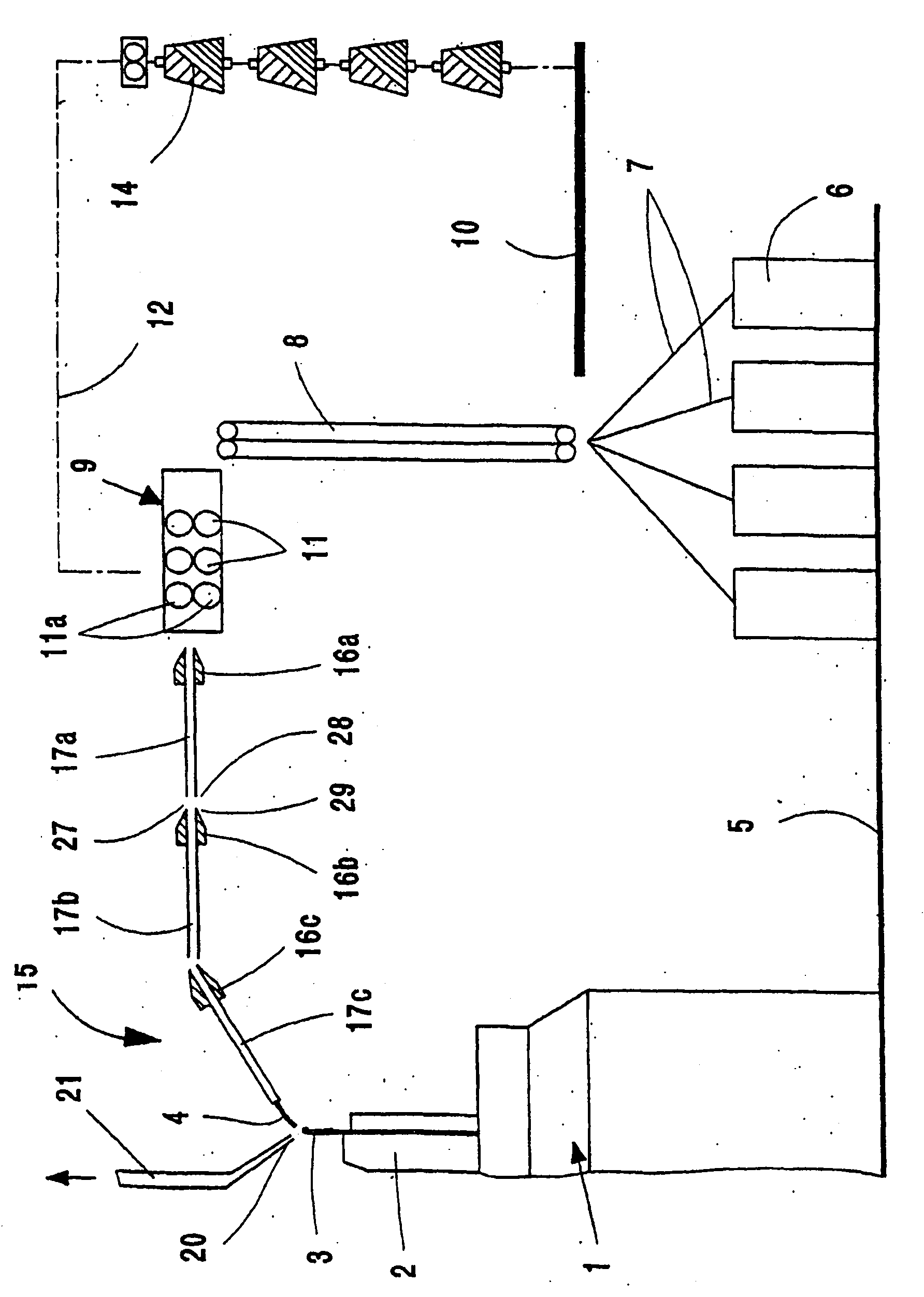
[0028] figure 1 Roughly schematically shown in a vertical partial section, a knitting machine in the form of a circular knitting machine 1 comprising a needle cylinder 2 in which conventional knitting needles 3 are movably supported, said needles hereinafter referred to as The knitting position, which is the knitting system, can be moved into a receiving position suitable for receiving the fiber material 4 by means of cams not described. The circular knitting machine 1 , which can be designed, for example, as a multi-triangle circular knitting machine, is located on the floor of the hall or needle hall, indicated by reference numeral 5 . An operator can operate the knitting machine 1 from the hall floor 5 . Furthermore, a plurality of cans 6 in which rovings 7 made of fibers are deposited are placed on the hall floor 5 .

[0029] The roving 7 is conveyed by means of a conveyor belt 8 or the like to a drafting device 9 accessible to the operator from a workbench 10 arranged a...


PUM


Abstract

A device for transporting fibre material between a drawing frame and a loop-forming machine is described. The device contains at least two transport units which are disposed in succession and have respectively one inlet- and outlet opening, said transport units being formed from respectively one twisting member (16a, 16b, 16c) and one transport pipe (17a, 17b, 17c) connected thereto, there being provided between an outlet end (28) of a preceding transport unit (16a, 17a) and the inlet end of a subsequent transport unit (16b, 17b) a gap (27a, 27b) which is intended for forming an air removal opening. According to the invention, a suction device (31a, 31b) is disposed in the region of this gap (27a, 27b) (FIG. 4).

Description

technical field [0001] The invention relates to a conveying device for conveying fibrous material between a drafting device and a knitting machine and to a circular knitting machine equipped with the conveying device. Background technique [0002] Devices of this type are especially known in combination with so-called spinning knitting machines, for example circular knitting machines (PCT WO 2004 / 079 068 A2, DE 10 2006 006 502 A1), which instead of the usual yarn Work with fiber materials that are as untwisted as possible. The fiber material used for knitting is converted into a temporary yarn directly after it has been discharged from the drafting device by means of a spinning device and a conveying device with a so-called twisting device, wherein the temporary twist of the fiber material is maintained during the entire conveying process. The temporary yarn delivery preferably takes place in a delivery tube connected to the twisting structure. In order to enable the draft...

Claims


Application Information

Patent Timeline
Patent Type & Authority Patents(China)
IPC IPC(8): D04B9/14D01H1/115D01H11/00
CPCD01H4/02D01H11/005D04B9/14D01H1/115
Inventor W・鲍尔A・弗拉德
Owner SIPRA PATENTENTWICKLUNGS & BET GMBH
Why Eureka
Try Eureka