

In-molded capacitive switch
An in-mold molding and capacitive technology, which is applied in the direction of electric switches, electronic switches, magnetic/electric field switches, etc., can solve the problems that capacitive switches cannot be integrated with profiling structures
- Summary
- Abstract
- Description
- Claims
- Application Information
AI Technical Summary
Problems solved by technology
Method used
Image

Examples
Embodiment Construction
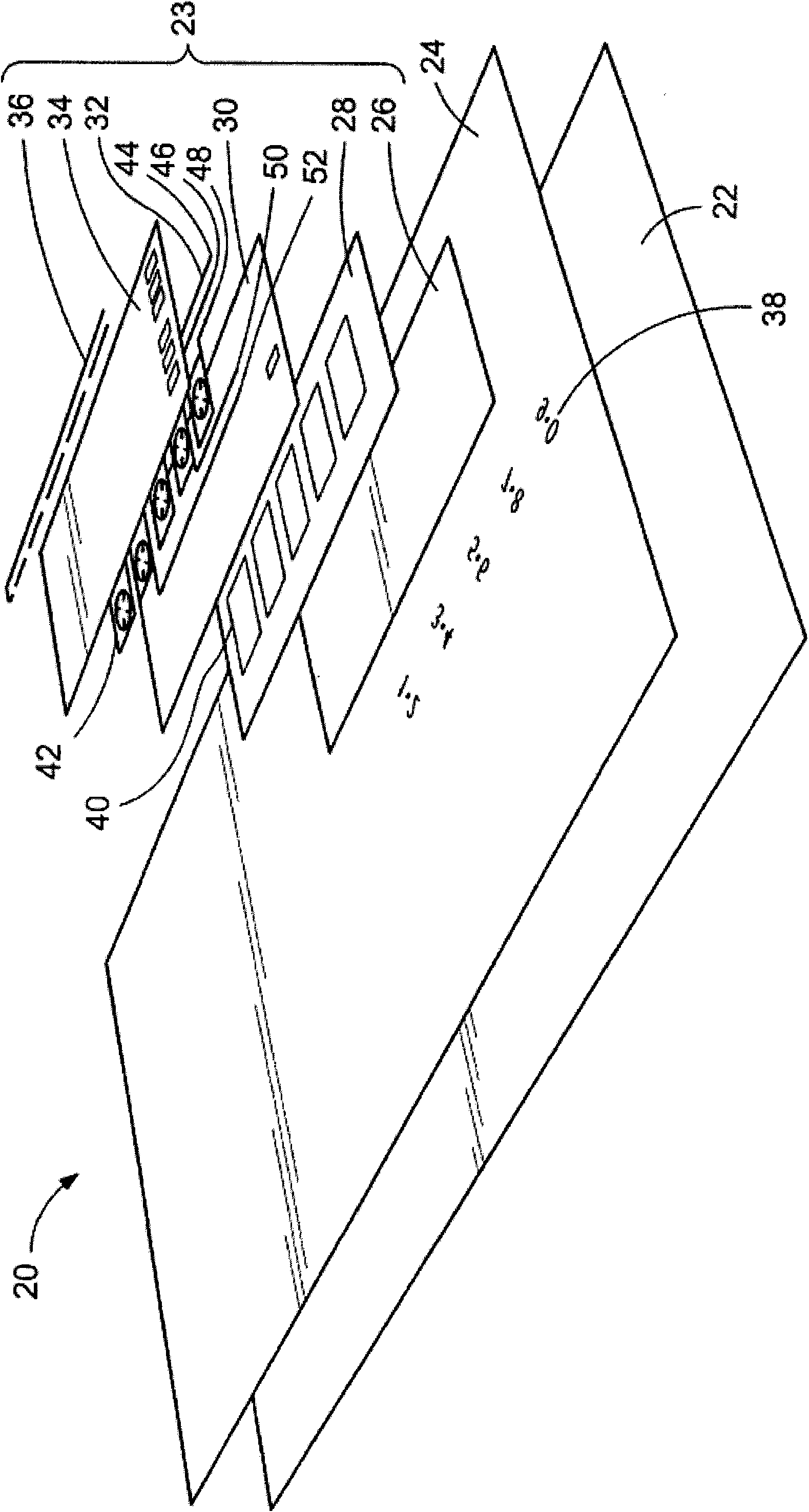
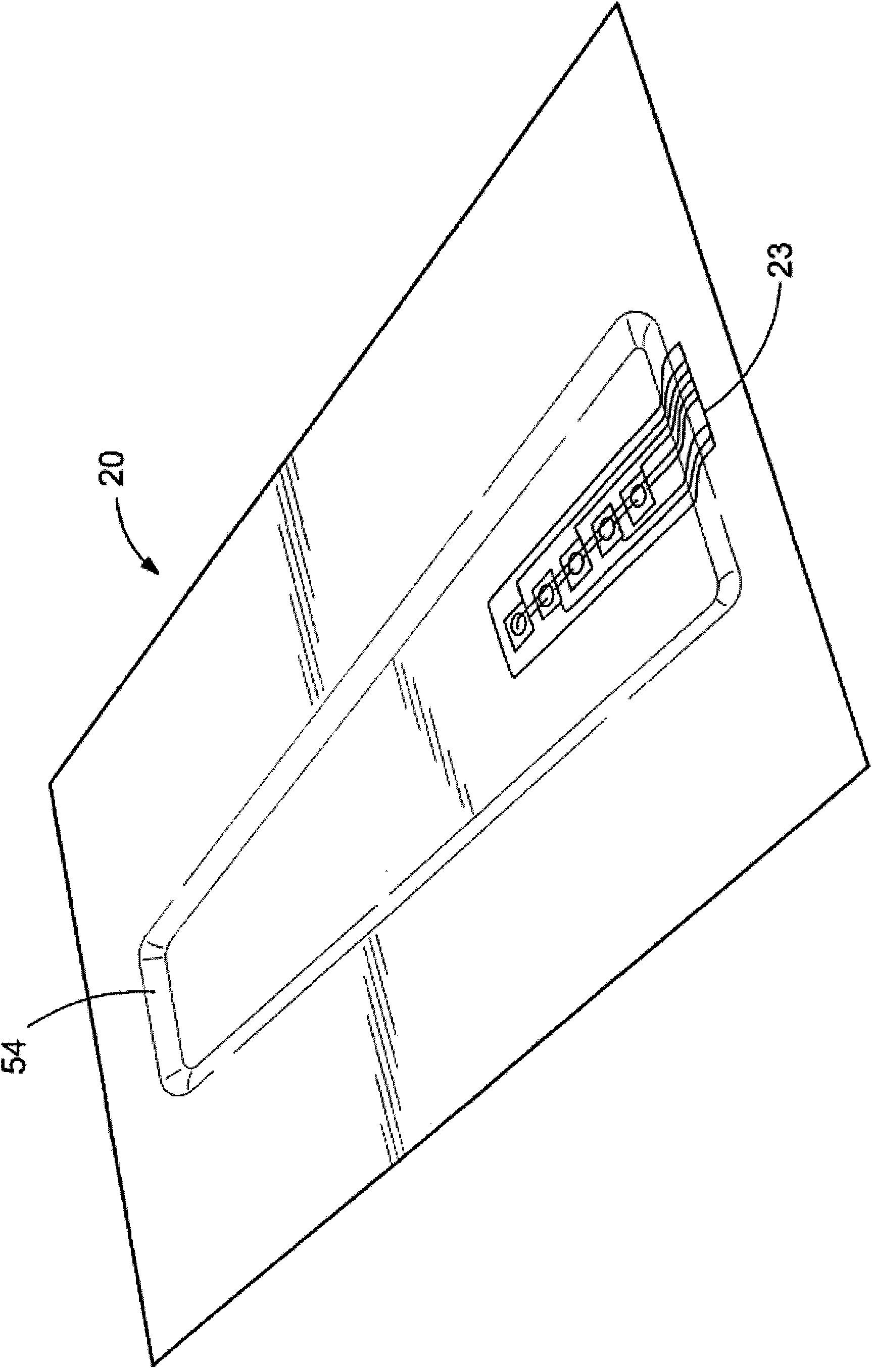
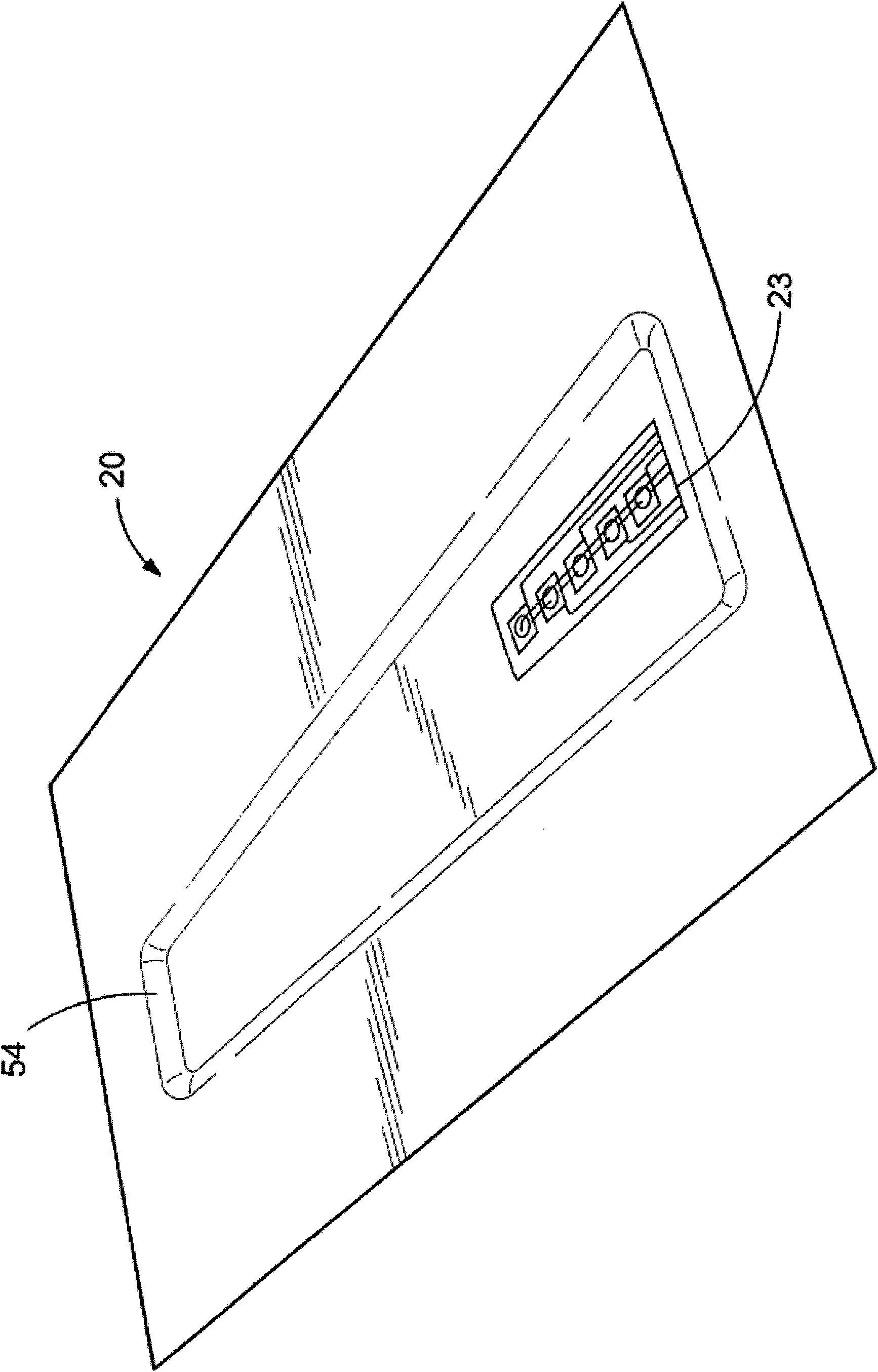
[0016] The present invention relates to in-moulded switching devices. A preferred embodiment involves an in-molded capacitive switch. In addition, capacitive switches can also be in-molded into three-dimensional structures. As mentioned above, capacitive switches detect changes in capacitance due to switching disturbances.
[0017] In one embodiment, when a conductive or charged object, such as a finger, is placed close to the sensing area, a change in the capacitance of the sensing area indicates that a switching action has occurred. A sensing circuit detects a change in capacitance of the sensing region. For example, sensing circuitry can be tuned to detect specific changes in capacitance. For example, the sensing circuitry can be tuned to detect the proximity of a finger to the sensing area while not detecting other types of disturbances (eg, moisture). U.S. Patent No. 5,972,623, filed October 21, 1997, to applicants Gupta et al., titled "Solid Capacitive Switches," dis...
PUM
 Abstract
Description
Claims
Application Information