Method for cleaning ceramic filter
A ceramic filter and filter plate technology, applied in the direction of filtration and separation, separation methods, chemical instruments and methods, etc., can solve the problems of inability to install safety facilities, transducer short circuit, safety hazards, etc., achieve the best cleaning effect, reduce The failure rate and the effect of convenient troubleshooting
Inactive Publication Date: 2010-08-25
YUNNAN DAHONGSHAN PIPELINE
View PDF8 Cites 2 Cited by
- Summary
- Abstract
- Description
- Claims
- Application Information
AI Technical Summary
Problems solved by technology
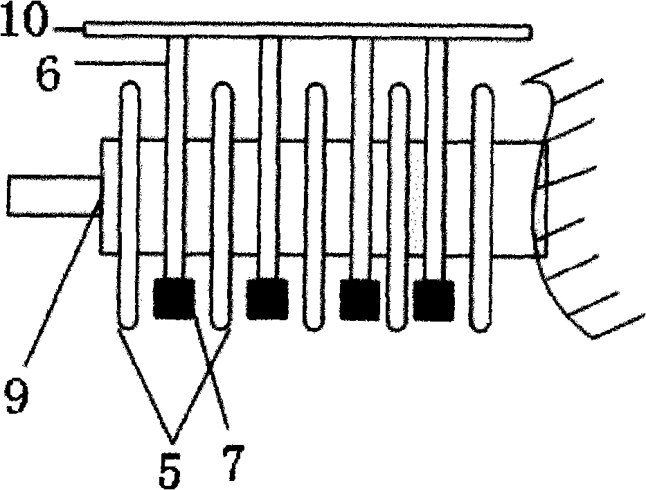
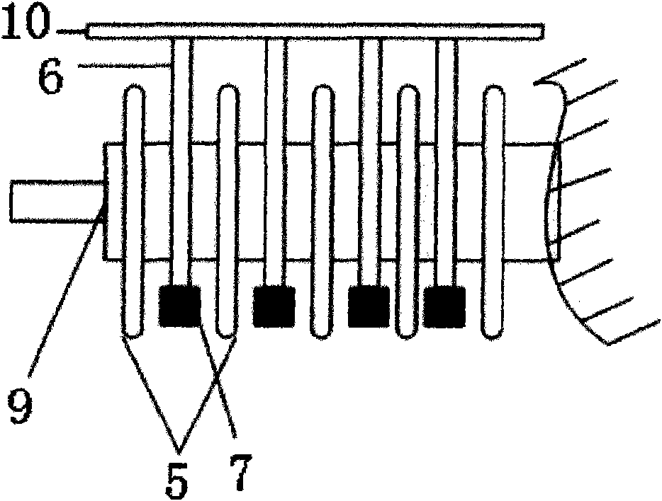
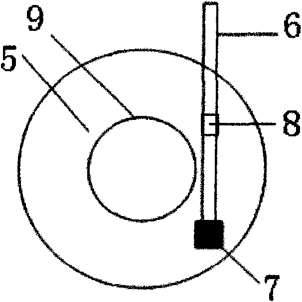
In the prior art, the ultrasonic transducer box is fixedly installed at the bottom of the trough, causing the ultrasonic transducer box to be soaked in the pulp for a long time, and the pulp is constantly stirred, causing frequent short circuits and wear of the transducer
Moreover, due to the small gap between the ceramic filter plate and the transducer box, the maintenance personnel cannot directly enter the tank to troubleshoot the ultrasonic transducer box. It is necessary to remove the ceramic plate for processing, and then install the ceramic plate after completion ;During the processing process, maintenance personnel are also required to cooperate under the silo, and the gap under the silo is also very small. Since it is impossible to install safety facilities, there are serious safety hazards
In addition, due to the fixed installation position of the ultrasonic transducer box, the ultrasonic transducer produces sound wave interference, and the positions of the peaks and valleys are fixed, so that part of the circular area of the ceramic filter plate has no ultrasonic vibration and cannot be cleaned. After running for a period of time, the ceramic filter plate There will be black and white permanent regeneration blind spots
Method used
View moreImage
Smart ImageViewing Examples

Examples
Embodiment Construction
Login to View More PUM
 Abstract
The invention relates to a method for cleaning a ceramic filter, which can facilitate maintenance of an ultrasonic transducer and has better cleaning effect. The invention adopts a technical scheme that: a filter plate of the ceramic filter is cleaned through the ultrasonic transducer. The method is characterized in that: a motor drives an ultrasonic transducer box to move up and down; the ultrasonic transducer box is positioned at different positions by controlling start or stop of the motor; and the filter plate is cleaned.
Description
A cleaning method for a ceramic filter technical field The invention relates to a cleaning method for a ceramic filter. Background technique Ceramic filter is a kind of concentrate dehydration equipment, which is widely used in metal mines and non-metal mines, such as iron ore, copper mine, gold mine, lead-zinc mine, phosphate mine, etc. Ceramic filter is a kind of high-efficiency and energy-saving solid-liquid separation equipment. It mainly uses microporous ceramic filter plate to dehydrate through vacuuming; microporous ceramic filter plate is a large-area porous ceramic filter plate with thin-walled hollow structure. The support ball is filled inside; the ceramic filter plate needs to be cleaned after being used for a period of time, and the cleaning is mainly performed by physical cleaning using ultrasonic vibration. In the prior art, the ultrasonic transducer box is fixedly installed at the bottom of the trough, causing the ultrasonic transducer box to be soaked i...
Claims
Login to View More Application Information
Patent Timeline
 Patent Type & Authority Applications(China)
IPC IPC(8): B01D29/41B01D29/72B01D33/21B01D33/54
Inventor 李幼灵王长勇张竹明吴建德潘春雷安建普光跃瞿承中杨鸿志
Owner YUNNAN DAHONGSHAN PIPELINE