Round hole centering circle tool
A technique for drawing circles and tools, applied in manufacturing tools, workshop equipment, etc., can solve the problems of inconvenient centering of large round holes, reducing machining accuracy, inaccurate centering and other problems, achieving simple structure, accurate centering, and easy installation. Effect
Inactive Publication Date: 2010-08-25
ZHEJIANG UNIV
View PDF7 Cites 6 Cited by
- Summary
- Abstract
- Description
- Claims
- Application Information
AI Technical Summary
Problems solved by technology
At present, the existing centering technology for round holes mainly adopts the shaft-through method, which is simple and easy to operate. This method is mainly used for contact measurement centering of smaller diameter holes, and it is inconvenient to use for centering of large round holes.
In addition, during factory processing, the center of the round hole must be determined. Generally, the center of the round hole is determined according to the size of the center of the circle relative to other parts. These methods are cumbersome, and the measured center of the circle is very inaccurate, which greatly reduces the processing accuracy.
Method used
View moreImage
Smart ImageViewing Examples
Examples
Embodiment Construction
Login to View More PUM
 Abstract
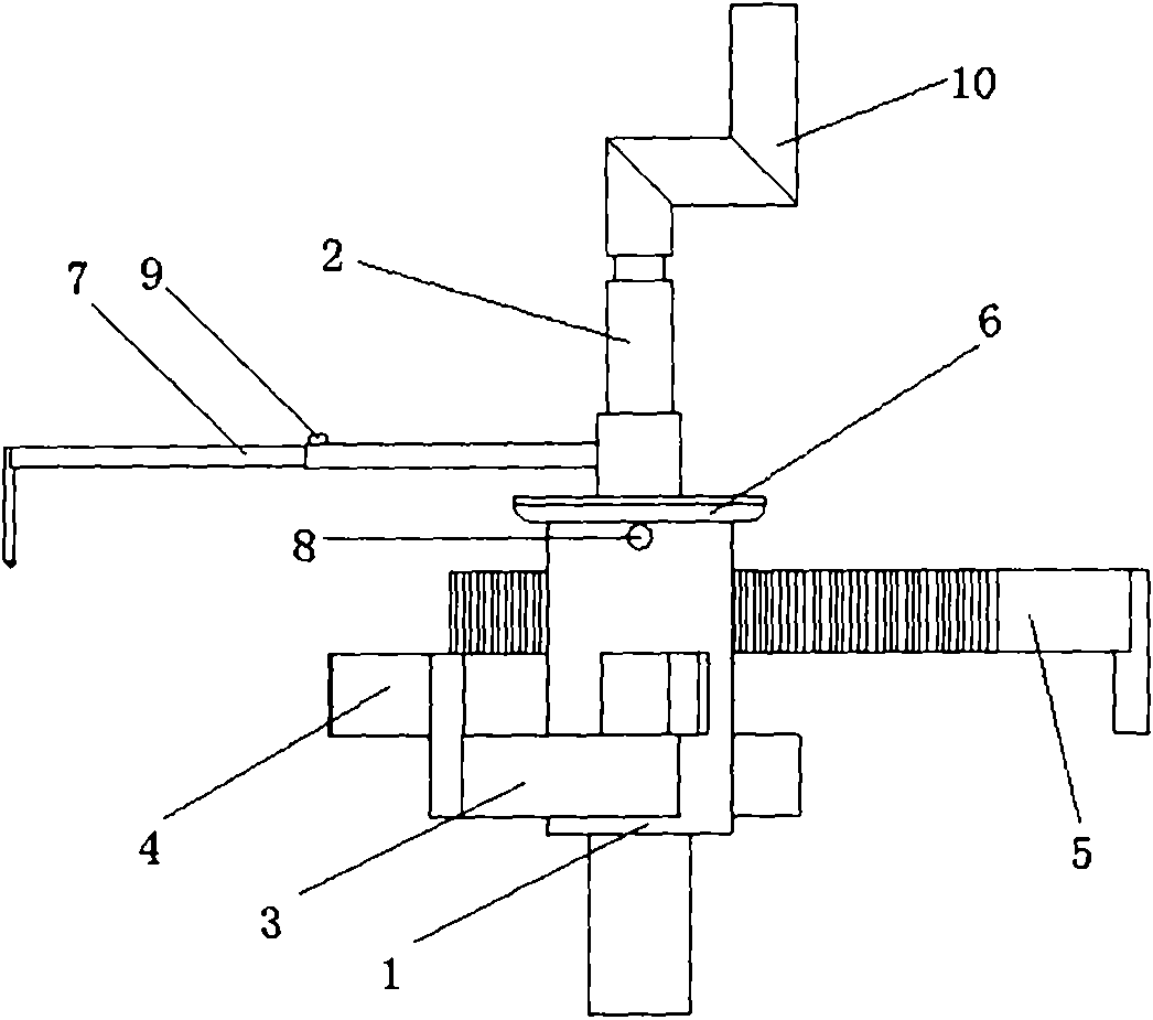
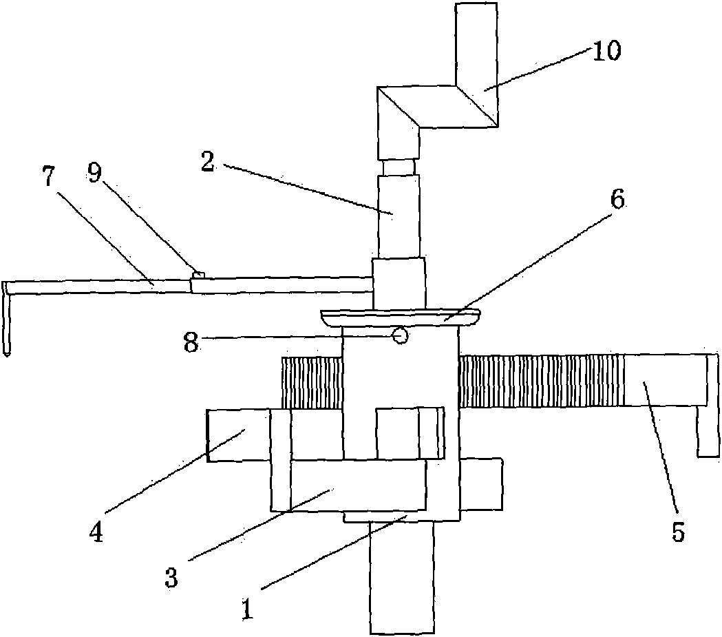
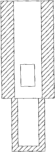
The invention discloses a round hole centering circle tool, which is used for centering round holes and describing circles on sections when round hole sections of different apertures are mechanically machined. The round hole centering circle tool mainly comprises a central shaft housing, a gear mandrel, a first rack arm, a second rack arm, a third rack arm, an angle dial, a staff circle describing arm, a fastening bolt, a fixing bolt, a handle and the like. The circle tool is suitable for centering inner holes of different apertures and describing the circles on the sections, in particular has more remarkable application effect on the inner holes of large apertures, has the characteristics of simple structure, simple and convenient mounting, simple operation method, accurate centering, convenient storage and convenient carrying, and can be used in relatively severer environments.
Description
Circle hole centering and drawing circle tool Technical field The invention relates to a circle drawing tool, in particular to a tool used for centering the circular hole and drawing a circle on the cross section when machining the circular hole cross section with different apertures. Background technique At present, the existing centering technology for round holes mainly adopts the through-shaft method, which is simple and easy to operate. This method is mainly used for contact measurement centering of smaller diameter holes, and it is inconvenient to use for centering of large round holes. In addition, when the factory is processing, the center of the hole must be determined. Generally, the center of the hole is determined according to the size of the center relative to other parts. These methods are cumbersome and the measured center is very inaccurate, which greatly reduces the processing accuracy. Summary of the invention The purpose of the present invention is to provi...
Claims
Login to View More Application Information
Patent Timeline
 IPC IPC(8): B25H7/04
Inventor 郭峰王进陆国栋费少梅
Owner ZHEJIANG UNIV
Features
- R&D
- Intellectual Property
- Life Sciences
- Materials
- Tech Scout
- Unparalleled Data Quality
- Higher Quality Content
- 60% Fewer Hallucinations
Learn More Browse by: Latest US Patents, China's latest patents, Technical Efficacy Thesaurus, Application Domain, Technology Topic, Popular Technical Reports.
© 2025 PatSnap. All rights reserved.Legal|Privacy policy|Modern Slavery Act Transparency Statement|Sitemap|About US| Contact US: help@patsnap.com


