
Shaft sleeve groove automatic polishing equipment

An automatic polishing and shaft sleeve technology, which is applied in the direction of grinding/polishing equipment, metal processing equipment, surface polishing machine tools, etc., can solve the problems of automatic loading and unloading, shaft sleeve groove deviation, and inaccurate centering, etc. problems, to achieve the effect of convenient loading and unloading, accurate centering of the workpiece, and high degree of automation

Active Publication Date: 2019-08-02
自贡中兴耐磨新材料有限公司
View PDF12 Cites 3 Cited by
  • Summary
  • Abstract
  • Description
  • Claims
  • Application Information

AI Technical Summary

Problems solved by technology

[0002] The shaft sleeve is an indispensable supporting wear-resistant sleeve for mechanical equipment. It can replace some rolling bearings or be used as a wear-resistant sleeve for rotating parts. According to the needs of use, the surface of the sliding bearing sleeve can be made into annular grooves of different sizes for To store lubricating oil, or install collars, etc., and then polish the groove. At present, there are polishing equipment, such as the patent No. CN201710927412.3 provides a "steel sleeve polishing machine", including a steel sleeve conveyor plate and two steel sleeves. The set of polishing wheels can continuously feed materials. The advantages are: continuous polishing can be realized, which greatly improves the work efficiency. The disadvantages are: the centering of this equipment is not accurate enough, the groove of the shaft sleeve will be biased after polishing, and it cannot automatically load and unload materials.

Method used


Image

  • Shaft sleeve groove automatic polishing equipment
  • Shaft sleeve groove automatic polishing equipment
  • Shaft sleeve groove automatic polishing equipment

Examples


Embodiment

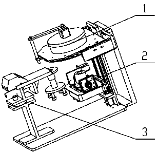
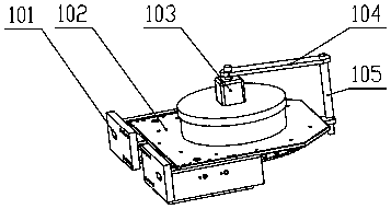
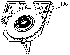
[0032] Such as figure 1 , figure 2 , image 3 , Figure 4 , Figure 5 , Figure 6 , Figure 7 , Figure 8 As shown, an automatic polishing equipment for shaft sleeve grooves, including: clamping and positioning device 1, polishing device 2 and automatic loading and unloading device 3;

[0033] The clamping and positioning device 1 is fixedly installed on the upper part of the polishing device 2, and it includes a clamping motor 103 and a splint 108. The clamping motor 103 rotates to drive the splint 108 to automatically clamp and position the bushing to be processed; The annular groove is polished, and it can move up and down to facilitate loading and unloading; the automatic loading and unloading device 3 is fixedly installed on the front end of the polishing device 2 to automatically load and unload the shaft sleeve; automatic loading when in use The power source 302 of the unloading device 3 drives the slewing bearing 303 to rotate, and then drives the upper frame 3...


PUM


Abstract

The invention provides shaft sleeve groove automatic polishing equipment. The equipment is characterized in that a clamping positioning device, a polishing device and an automatic feeding and discharging device are included; the clamping positioning device is fixedly installed on the upper portion of the polishing device and comprises a clamping motor and a clamping plate, and the clamping motor is rotated to drive the clamping plate to automatically clamp and position a to-be-processed shaft sleeve; an annular groove formed in the surface of the shaft sleeve is automatically polished by the polishing device, the polishing device can move up and down to make feeding and discharging convenient, the automatic feeding and discharging device are fixedly installed at the front end of the polishing device to automatically feed and discharge materials for the shaft sleeve.

Description

technical field [0001] The invention relates to the technical field of machining automation, in particular to an automatic polishing equipment for shaft sleeve grooves. Background technique [0002] The shaft sleeve is an indispensable supporting wear-resistant sleeve for mechanical equipment. It can replace some rolling bearings or be used as a wear-resistant sleeve for rotating parts. According to the needs of use, the surface of the sliding bearing sleeve can be made into annular grooves of different sizes for To store lubricating oil, or install collars, etc., and then polish the groove. At present, there are polishing equipment, such as the patent No. CN201710927412.3 provides a "steel sleeve polishing machine", including a steel sleeve conveyor plate and two steel sleeves. The set of polishing wheels can continuously feed materials. The advantages are: continuous polishing is realized, which greatly improves the work efficiency. The disadvantages are: the centering of ...

Claims


Application Information

Patent Timeline
Patent Type & Authority Applications(China)
IPC IPC(8): B24B29/02B24B41/06B24B41/00B24B47/06B24B27/00
CPCB24B27/0076B24B29/02B24B41/005B24B41/06B24B47/06
Inventor 张学河
Owner 自贡中兴耐磨新材料有限公司
Learn More