Continuous rotating automatic centering hydraulic clamping mechanism and hydraulic control system thereof

A hydraulic clamping and automatic centering technology, which is applied in the direction of manufacturing tools, metal processing, metal processing equipment, etc., can solve the problems of difficult synchronous clamping, low work efficiency, rotational torque changes, etc., and achieve thread connection and thread disassembly The effect of shortening time, improving work efficiency, and large layout space

Inactive Publication Date: 2015-03-25
JIANGYIN DONGCHEN PETROLEUM DRILLING EQUIP
View PDF10 Cites 3 Cited by
  • Summary
  • Abstract
  • Description
  • Claims
  • Application Information

AI Technical Summary

Problems solved by technology

One group is fixed after being clamped, and the entire clamping system of the other group needs to rotate with a large torque to tighten or disassemble the connecting thread of the shell. Since there are many clamping cylinders, and the clamping process is very It is difficult to achieve synchronization, so it is difficult to achieve multi-cylinder synchronous clamping and continuous high-torque rotation
At present, the disassembly and assembly equipment of the stator shell of screw drilling tools at home and abroad generally use the other two oil cylinders to apply high torque intermittently and repeatedly rotate (10 to 14 oil cylinders are used for clamping and rotation), and each action can only rotate less than 35° rotation angle, and the rotation torque changes due to the change of the rotation arm
In general, the threaded connection of the stator shell requires more than ten threads, so the working efficiency of this kind of equipment is very low.
In addition, the two sets of oil cylinders (clamping fixed and clamping rotation) of this disassembly and assembly equipment, because there are many clamping oil cylinders and it is not easy to clamp synchronously, the center of rotation is seriously not concentric, which causes great difficulties for the threaded connection of the stator shell.

Method used


Image

  • Continuous rotating automatic centering hydraulic clamping mechanism and hydraulic control system thereof
  • Continuous rotating automatic centering hydraulic clamping mechanism and hydraulic control system thereof
  • Continuous rotating automatic centering hydraulic clamping mechanism and hydraulic control system thereof

Examples


Embodiment Construction

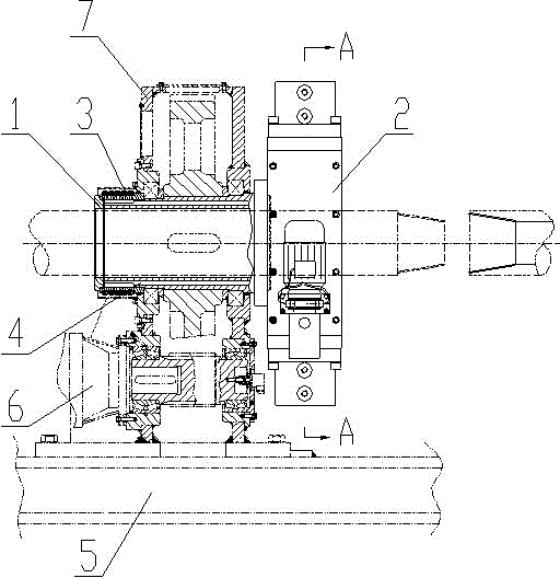
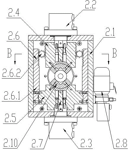
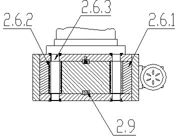
[0050] see Figure 1~Figure 5 , the present invention is a continuously rotating self-centering hydraulic clamping mechanism, which includes a hollow main shaft 1 and a clamping mechanism 2, the clamping mechanism 2 is fixedly arranged on the rear end of the hollow main shaft 1, and the clamping mechanism 2 includes a clamping Mechanism frame body 2.1, the top and bottom of the clamping mechanism frame body 2.1 are respectively provided with an upper clamping oil cylinder 2.2 and a lower clamping oil cylinder 2.3, the upper clamping oil cylinder 2.2 and the lower clamping oil cylinder 2.3 are arranged oppositely, the upper Clamping cylinder 2.2 is provided with upper slider 2.4, said lower clamping cylinder 2.3 is provided with lower slider 2.5, said upper slider 2.4 and lower slider 2.5 are provided with V-shaped block 2.10, said upper slider A rack and pinion synchronous mechanism 2.6 is set between the block 2.4 and the lower block 2.5, a miniature hydraulic station 2.8 is ...


PUM


Abstract

The invention relates to a continuous rotating automatic centering hydraulic clamping mechanism and a hydraulic control system thereof. The mechanism comprises a hollow main shaft (1) and a clamping mechanism (2), wherein the clamping mechanism (2) comprises a clamping mechanism frame body (2.1); an upper clamping cylinder (2.2) and a lower clamping cylinder (2.3) are arranged on the clamping mechanism frame body (2.1); an upper sliding block (2.4) and a lower sliding block (2.5) are respectively arranged on the upper clamping cylinder (2.2) and the lower clamping cylinder (2.3); V-shaped blocks (2.10) are arranged on the upper sliding block (2.4) and the lower sliding block (2.5); a gear and rack synchronizing mechanism (2.6) is arranged between the upper sliding block (2.4) and the lower sliding block (2.5). The continuous rotating automatic centering hydraulic clamping mechanism and the hydraulic control system thereof are simple in motion and accurate in centering, and can continuously rotate in forward and reverse directions, greatly shorten the connection and disassembly time for a stator casing, and greatly improve the operating efficiency.

Description

technical field [0001] The invention relates to a continuously rotating self-centering hydraulic clamping mechanism and a hydraulic control system thereof, which are used for thread connection and thread disassembly of a screw drilling tool stator casing used in petroleum exploitation, and belong to the technical field of petroleum exploitation equipment. Background technique [0002] Drilling tools for oil exploration are usually made of high-strength connections between the upper and lower sections through internal and external threads at the end, such as the threaded connection of the stator shell of the screw drilling tool drill collar. This threading and disassembly requires a lot of torque to complete. Especially in the drill collar stator casing after drilling in the oil field, because the thread is very tightly connected and severely corroded, it needs a larger dismantling torque to dismantle this thread. [0003] Since the outer wall of the stator housing of the sc...

Claims


Application Information

Patent Timeline
Patent Type & Authority Applications(China)
IPC IPC(8): B23P19/06
CPCB23P19/06
Inventor 荣彬彬刘成龙刘正民
Owner JIANGYIN DONGCHEN PETROLEUM DRILLING EQUIP
Why Eureka
Try Eureka